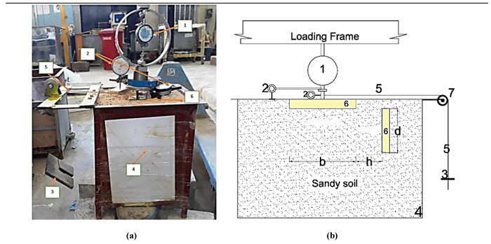
Fig. (1) A general view of the model*. (a) Photo for the test setup. (b) Drawing of the test setup.
*The details of the general view of the model as marked of 7 numbers, are listed below:
1-proving ring to read the static vertical load
2-dail gauge to read the vertical and lateral movement
3-known weight to apply lateral loads.
4-steel box
5-wire steel was connected to the footing lateral load
6-steel footing with dimensions 50 × 50 × 10 mm
7-steel pulley