- Home
- About Journals
-
Information for Authors/ReviewersEditorial Policies
Publication Fee
Publication Cycle - Process Flowchart
Online Manuscript Submission and Tracking System
Publishing Ethics and Rectitude
Authorship
Author Benefits
Reviewer Guidelines
Guest Editor Guidelines
Peer Review Workflow
Quick Track Option
Copyediting Services
Bentham Open Membership
Bentham Open Advisory Board
Archiving Policies
Fabricating and Stating False Information
Post Publication Discussions and Corrections
Editorial Management
Advertise With Us
Funding Agencies
Rate List
Kudos
General FAQs
Special Fee Waivers and Discounts
- Contact
- Help
- About Us
- Search


The Open Fuels & Energy Science Journal
(Discontinued)
ISSN: 1876-973X ― Volume 11, 2018
Exergy Assessment of a Solar-Assisted District Energy System
Behnaz Rezaie1, *, Bale V. Reddy2, Marc A. Rosen2
Abstract
Background:
District Energy (DE) is a technology capable of using renewable energy (e.g., solar thermal systems) and waste heat as energy sources efficiently. DE technology nonetheless has potential for improvement. Thermal Energy Storage (TES) can enhance DE performance significantly.
Objective:
An exergy analysis of a DE system which includes a solar thermal energy system and TES is performed, so as to improve understanding of its performance.
Method:
A case study based on the Friedrichshafen DE system in Germany is used to assess thermodynamically the role of solar energy and TES in a DE system. The system performance is separated into three modes: (1) fossil fuel is the only source of energy, (2) a discharging TES and fossil fuel provide heat for the DE system, and (3) solar energy and fossil fuels are the energy supplies. Exergy analyses are conducted for each performance mode and the overall DE system.
Results:
The results quantify the benefits of incorporating solar energy and TES on the performance of the Friedrichshafen DE system, and demonstrate that the overall exergy efficiency of the DE system increases from 23% to 27% with assistance of solar thermal collectors and TES, while the total energy efficiency increases from 83% to 87%.
Conclusion:
An increase of exergy efficiency is observed when TES is added to a DE system, due to a reduction in solar thermal energy loss by the TES, which allows more solar energy to be converted to useful energy to satisfy the DE system thermal energy demand.
Article Information

Identifiers and Pagination:
Year: 2018Volume: 11
First Page: 30
Last Page: 43
Publisher Id: TOEFJ-11-30
DOI: 10.2174/1876973X01811010030
Article History:
Received Date: 20/10/2017Revision Received Date: 20/01/2018
Acceptance Date: 22/01/2018
Electronic publication date: 30/03/2018
Collection year: 2018
open-access license: This is an open access article distributed under the terms of the Creative Commons Attribution 4.0 International Public License (CC-BY 4.0), a copy of which is available at: https://creativecommons.org/licenses/by/4.0/legalcode. This license permits unrestricted use, distribution, and reproduction in any medium, provided the original author and source are credited.
* Address correspondence to this author at the Department of Mechanical Engineering, College of Engineering, University of Idaho, Behnaz Rezaie, 875 Perimeter Dr., Moscow, USA; Tel: 208-885-1026; Email: Rezaie@uidaho.edu
| Open Peer Review Details | |||
|---|---|---|---|
| Manuscript submitted on 20-10-2017 |
Original Manuscript | Exergy Assessment of a Solar-Assisted District Energy System | |
1. INTRODUCTION
Various measures for addressing environmental problems have been proposed. For instance, Robins [1Robins, J. The new good life: Living better than ever in an age of less., 2010, ] describes various practical approaches to reduce Green House Gas (GHG) emissions, while Rosen [2Rosen, M.A. Combatting global warming via non-fossil fuel energy options. Int. J. Glob. Warm., 2009, 1(1-3), 2-28.] describes methods to combat global warming through non-fossil fuel energy alternatives. A common approach is using energy more efficiently, on the basis of energy and, in particular, exergy. The thermodynamic quantity exergy is defined as the maximum work of a flow or system relative to a reference environment, or, more loosely, as the valuable part of energy [3Schmidt, D. Low exergy systems for high-performance buildings and communities. Energy Build., 2009, 41(3), 331-336.]. Exergy analysis can help identify opportunities to increase the efficiency of a process or system. The temperature, pressure and chemical composition of a flow or system and of the reference environment both affect the exergy content of a material or energy flow [4Moran, M.J. Availability analysis is a guide to efficient energy use. Corrected Edition., 1989, ]. Annex 49 [5Annex 49. Energy conservation in buildings and community systems-Low exergy systems for high-performance buildings and communities, http://www.annex49.com/background.html (Accessed 5 March 2018).] suggests using a combined energy and exergy analysis as a new method of designing energy supply systems in buildings for the use of renewable and low temperature heat sources.
District energy is a technology which can use renewable energy and waste heat as a source of energy. Using low-temperature heat from renewable energy sources, such as solar and geothermal energy, as well as industrial waste heat, in district heating has proven to be attractive [6Bloomquist, R.G. Geothermal space heating. Geoth, 2003, 32(4-6), 513-526.-10Hepbasli, A.; Canakci, C. Geothermal district heating applications in Turkey: A case study of Izmir-Balcova. Energy Convers. Manage., 2003, 44(8), 1285-1301.]. Rezaie and Rosen [11Rezaie, B.; Rosen, M.A. District heating and cooling: Review of technology and potential enhancements. Appl. Energy, 2012, 93, 2-10.] and Lake et al . [12Lake, A.; Rezaie, B.; Beyerlein, S. Review of district heating and cooling systems for a sustainable future. Renew. Sustain. Energy Rev., 2017, 67, 417-425.] describe District Energy (DE) technology and its potential for improvement. Efficiency can be improved by using energy saving equipment [13Patil, A.; Ajah, A.; Herder, P. Recycling industrial waste heat for sustainable district heating: A multi-actor perspective. Int. J. Environ. Technol. Manag., 2009, 10, 412-426.] and recovering industrial waste heat [14Casten, T.R.; Ayers, R.U. Recycling energy: Growing income while mitigating climate change, Report, Recycled Energy Development, 2017, ], and such measures usually reduce GHG and other emissions [13Patil, A.; Ajah, A.; Herder, P. Recycling industrial waste heat for sustainable district heating: A multi-actor perspective. Int. J. Environ. Technol. Manag., 2009, 10, 412-426.]. According to the U.S. Department of Energy [15Cogeneration or combined heat and power., 2003, ], district heating can considerably reduce GHG emissions. Lund et al . [16Lund, H.; Moller, B.; Mathiesen, B.V.; Dyrelund, A. The role of district heating in future renewable energy systems. Energ, 2003, 32, 1381-1390.] state that DE not only decreases carbon dioxide (CO2) emissions but also results in significant decreases in overall costs of energy systems. An example of integrating a DE system with renewable energy is the use of solar collectors consisting of vacuum tubes to generate heat for DE; this technology is popular in Europe and helps reduce GHG emissions. Other solar thermal collectors can also be used to convert solar energy to heat for DE applications. Many investigations of solar collectors and their applications have been conducted in recent years [17Li, Y.; Liu, G.; Liu, X.; Liao, S. Thermodynamic multi-objective optimization of a solar-dish Brayton system based on maximum power output, thermal efficiency and ecological performance. Renew. Energy, 2016, 95, 465-473.].
DE systems have been used in Europe since the 14th century, with one geothermal district heating system in continuous operation in France (Chaudes-Aigues thermal station) since that time [18Lemale, J.; Jaudin, F. La geothermie, une energie d’avenir, une realite en Ile de France., 1999, Geothermal heating, an energy of the future, a reality in Ile-de-France]. The US Naval Academy constructed the first district system in USA on its Annapolis campus in 1853, and the commercial district heating system in New York was built in 1877 [19Marinova, M.; Beaudry, C.; Taoussi, A.; Trepanier, M.; Paris, J. Economic assessment of rural district heating by bio-steam supplied by a paper mill in Canada. Bull. Sci. Technol. Soc., 2008, 28(2), 159-173.]. The first district energy system in Canada was built in Winnipeg’s commercial core in 1924 [19Marinova, M.; Beaudry, C.; Taoussi, A.; Trepanier, M.; Paris, J. Economic assessment of rural district heating by bio-steam supplied by a paper mill in Canada. Bull. Sci. Technol. Soc., 2008, 28(2), 159-173.]. Northern European countries are the main users of district energy systems. For instance, Sweden has installed a 40-TWh district heating system that supplied more than half of the heating capacity of the country in 2000 [20Gebremedhin, A. The role of a paper mill in a merged district heating system. Appl. Therm. Eng., 2003, 23, 769-778.]. The percentage of district-heated homes is around 65% in Latvia and Lithuania. Due to use of district energy networks, the use of oil and hydroelectricity has dropped about 10% in Norway [21Pavlas, M.; Stehlik, P.; Oral, J.; Sikula, J. Integrating renewable sources of energy into an existing combined heat and power system. Energ, 2006, 31, 2499-2511.]. Soltani et al . [22Soltani, R.; Dincer, I.; Rosen, M.A. Thermodynamic analysis and performance assessment of an integrated heat pump system for district heating applications. Appl. Therm. Eng., 2015, 89, 833-842.] thermodynamically analyzed an integrated heat pump system for district heating applications.
Andrepont [23Andrepont, J.S. Maximize district energy value by leveraging technology options. District Energy, 2006, 92(4), 40-41.] states that using DE in conjunction with other energy technologies enhances overall system efficiency. Rezaie et al . [24Rezaie, B.; Reddy, B.V.; Rosen, M.A. Role of thermal energy storage in district energy systems.Energy Storage., 2011, ] assess the positive role of Thermal Energy Storage (TES) in a DE system from the perspectives of environmental impact and fossil fuel consumption. Kharseh and Nordell [25Kharseh, M.; Nordell, B. Sustainable heating and cooling systems for agriculture. Int. J. Energy Res., 2011, 35, 415-422.] interpret TES as a bridge between periods of energy demand from the DE system and periods of energy supply to the DE system. TES can enhance the performance of DE systems significantly. Rad et al . [26Rad, F.M.; Fung, A.S.; Rosen, M.A. An integrated model for designing a solar community heating system with borehole thermal storage. Energy Sustain. Dev., 2017, 36C, 6-15.] developed an integrated model for designing a solar community heating system with borehole thermal storage, while Sapińska-Śliwa et al . [27Sapińska-Śliwa, A.; Rosen, M.A.; Gonet, A.; Śliwa, T. Deep borehole heat exchangers: a conceptual review. Int. J. Air-Cond. Ref., 2016, 24(1), 1630001.] critically reviewed the deep borehole heat exchangers used in underground thermal energy storage.
A common approach to address concerns regarding CO2 and other harmful emissions is to reduce these emissions, and a common approach is to use energy resources more efficiently. Exergy analysis can facilitate this approach, as it permits investigations into the quality of energy and often suggests modifications to improve energy systems. Many applications of exergy analysis have been reported [28Jiaqiang, E.; Zuo, W.; Liu, X.; Peng, Q.; Deng, Y.; Zhu, H. Effects of inlet pressure on wall temperature and exergy efficiency of the micro-cylindrical combustor with a step. Appl. Energy, 2016, 175, 337-345.].
Here, a case study is used to assess thermodynamically the role of solar energy and TES in a DE system. The case study considered is the Friedrichshafen DE system in Germany. The TES stores the surplus solar energy until it is needed by thermal energy users of the DE system. Utilizing solar energy allows the DE system to use significantly less fossil fuel than would otherwise be the case. Seasonal TES, which normally requires significant thermal insulation to adequately reduce thermal losses, is used in the DE system. Originally, the Friedrichshafen DE system used only natural gas boilers. When a second residential area was added to the user base, solar thermal flat panels were added to provide energy for the entire thermal network. Energy and exergy analysis of TES in the Friedrichshafen DE system have been performed for a TES in a mixed condition [29Rezaie, B.; Reddy, B.V.; Rosen, M.A. Seasonal stratified thermal energy storage exergy analysis. Building Simulation Conference, Halifax, NS, CanadaMay 1-4, 2012] and in a stratified condition [30Rezaie, B.; Reddy, B.V.; Rosen, M.A. Exergy assessment of the use of thermal storage in a district energy system: Case study seasonal stratified thermal energy storage exergy analysis. Proc. INNOSTOCK 2012: 12th International Conference on Energy Storage, Lleida, Spain, May 16-18, 2012.]. Here, some results from latter studies on Friedrichshafen TES are used to perform an exergy analysis on the Friedrichshafen DE, with the objective of identifying for the Friedrichshafen DE the benefits of using TES and renewable energy.
2. MODELING AND ANALYSIS
In this study, we apply energy and exergy analyses to the Friedrichshafen DE system and its various possible operation modes during a year, and determine energy and exergy efficiencies for the system during the different operating modes.
A simplified model is developed for a DE system which utilizes solar thermal energy and TES which is representative of the Friedrichshafen DE system and which facilitates thermodynamic analysis (Fig. 1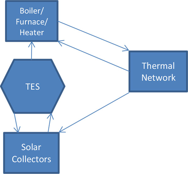 ). In this system solar collectors and a fossil fuel heater (boiler, furnace, or heater) provide energy for the DE system. During some periods, the solar collectors provide more thermal energy more than the demand and the excess energy is stored in the TES. When solar collectors cannot provide sufficient solar energy, the TES releases stored energy to the DE system. Arrows show the direction of the energy via heated fluid. (Fig. 1) shows all possible modes for the Friedrichshafen DE system. Each mode is explained with energy movement direction in the following sections.
 |
Fig. (1) Simplified illustration of a solar assisted DE system, showing flows of energy. |
2.1. Energy and Exergy Analysis
Exergy analysis is used to assess efficiencies and losses for energy systems. It permits investigations into the quality of energy and often suggests modifications to improve energy systems and reduce environmental impact [31Rosen, M.A.; Dincer, I. Exergoeconomic analysis of power plants operating on various fuels. Appl. Therm. Sci, 2003, 23, 643-658.-34Dincer, I.; Al-Muslim, H. Thermodynamic analysis of reheat cycle steam power plants. Int. J. Energy Res., 2005, 25, 727-739.], and provides insights that complement those from conventional energy analyses. Exergy analysis is a useful tool to investigate lost exergy in DE system, as Compton and Rezaie [35Compton, M.; Rezaie, B. Enviro-exergy sustainability analysis of boiler evolution in district energy system. Energy, 2017, 119, 257-265.] found through an application to a DE system fed by a biofuel. Also, Rezaie et al . [36Rezaie, B.; Reddy, B.V.; Rosen, M.A. Exergy analysis of thermal energy storage in a district energy application. Renew. Energy, 2015, 74, 848-854.] used exergy analysis for DE integrated with TES.
An energy balance for a general thermal system can be expressed as [37Dincer, I.; Rosen, M.A. Thermal energy storage: Systems and applications., (2nd ed. ), 2011, , 38Dincer, I.; Rosen, M.A. Exergy: Energy, environment and sustainable development., (2nd ed. ), 2013, ]:
 |
(1) |
Where,
 |
(2) |
A corresponding general exergy balance can be written as follows:
 |
(3) |
Where,
 |
(4) |
Energy and exergy balances are written for the solar assisted DE system in (Fig. 1) using these equations.
2.2. Operating Modes
The DE system, which is assisted by solar thermal energy and coupled with a TES, has three main operating modes, each of which is described separately in this section:
- Mode 1: The DE system uses fossil fuel only.
- Mode 2: The TES releases stored thermal energy to the DE system and is complemented by fossil fuel.
- Mode 3: The DE system is driven by solar energy and fossil fuel.
It should be explained that there is another mode which solar collectors generates energy more than the DE system demand. In this mode the excess heat stores into the TES system. This mode is exactly storage stage of the TES. This stage was calculated already in general [29Rezaie, B.; Reddy, B.V.; Rosen, M.A. Seasonal stratified thermal energy storage exergy analysis. Building Simulation Conference, Halifax, NS, CanadaMay 1-4, 2012] and in a stratified condition [30Rezaie, B.; Reddy, B.V.; Rosen, M.A. Exergy assessment of the use of thermal storage in a district energy system: Case study seasonal stratified thermal energy storage exergy analysis. Proc. INNOSTOCK 2012: 12th International Conference on Energy Storage, Lleida, Spain, May 16-18, 2012.] and those results are used in the present study. In this mode, just solar collectors and the TES are involve, the thermal network is out of this performance and that is the reason this mode is not considered as Mode 4 for the Friedrichshafen DE system.
2.2.1. Operating Mode 1
In operating Mode 1 (Fig. 2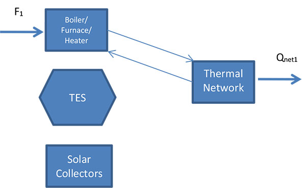 ), natural gas is the only source of heating. The solar panels and the TES do not operate. Circulating media flows to the thermal network where it transfers heat to users, and returns at a lower temperature to the boilers. The temperature at the inlet to the boilers is almost the same as that of the returned circulating media from the thermal network. Energy losses for pumps, valves, splitters and pipes are small so they are neglected throughout. Mode 1 occurs when the TES is discharged and the available solar energy is either insufficient or unavailable to satisfy the DE system demand.
In the thermodynamic analysis, each component is considered within a control volume for all modes. In (Fig. 2), F1 is the energy supplied by the natural gas and Qnet1 is the useful energy delivered to the consumer. Applying equations (1) and (2) to the Mode 1 operating period, Qnet1 can be expressed as:
 |
Fig. (2) Operating Mode 1 for a DE system assisted by solar thermal and TES, showing flows of energy. |
 |
(5) |
where Qloss-TN denotes the energy loss of the thermal network, and Q1 is the energy supplied by natural gas to the DE system by a fossil fuel heater (e.g., boiler, furnace, heater) having an energy efficiency ηh that can be expressed as follows:
 |
(6) |
The energy efficiency of the DE system for the Mode 1 can be expressed as:
 |
(7) |
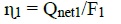
An exergy analysis of the solar assisted DE system for operating Mode 1 is carried out, using (Figs. 2 and 3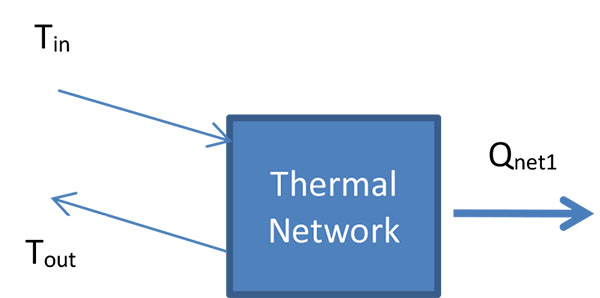 ). The latter shows the circulating media flows in the DE thermal network. The exergy of the net energy demand for Mode 1, ExQnet1, can be determined as:
 |
(8) |
Here, hout and hin are specific enthalpies of the circulating media outlet from and inlet to the thermal network respectively (Fig. 3), and sout and sin are the corresponding specific entropies. Also, T0 denotes the temperature of the reference environment, and m1 is the mass of the circulating media that passes through the thermal network during the period of operation, which can be determined as follows:
 |
Fig. (3) Thermal network during operating Mode 1, showing flows of energy. |
 |
(9) |
where, ΔT is temperature difference between the inlet from and outlet to the thermal network, and Cp denotes the specific heat at constant pressure of the flow m1. The exergy of the flow F1, ExF1, can be expressed as:
 |
(10) |
Where, R is the energy grade function for the fuel. Rosen et al. [32Rosen, M.A.; Le, M.N.; Dincer, I. Efficiency analysis of a cogeneration and district energy system. Appl. Therm. Eng., 2005, 25, 147-159.] report a value of 0.913 for the energy grade function natural gas. The exergy efficiency for the system during Mode 1, Ψ1, can be written as:
 |
(11) |
2.2.2. Operating Mode 2
In operating Mode 2 (Fig. 4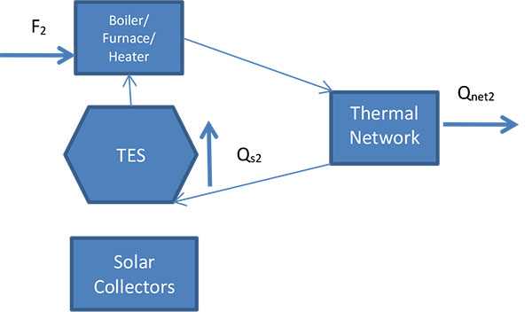 ), TES operation is added to the system described in operating Mode 1 (but solar collectors are not operating). The storage media in the TES is already heated by extra energy from the solar thermal collectors after feeding the DE system. The preheated storage media from the TES flows through the fossil fuel heater. The circulating media receives energy partially from fossil fuel and partially from the TES, which discharges its stored surplus solar energy to the DE system because there is a large energy demand for solar energy is unavailable.
In (Fig. 4), F2 is the fossil fuel energy input to the control volume, Qs2 is the thermal energy discharged from the TES and Qnet2 is the useful energy product for Mode 2. With equations (1) and (2), we can write:
 |
Fig. (4) Operating Mode 2 for a DE system assisted by solar thermal and TES, showing flows of energy. |
 |
(12) |
 |
(13) |
where Q2 denotes the energy from the fossil fuel that is input to the thermal network in Mode 2, and Qrec is the total energy recovered in the TES discharge stage. Details of Qrec are given by Rezaie et al . [30Rezaie, B.; Reddy, B.V.; Rosen, M.A. Exergy assessment of the use of thermal storage in a district energy system: Case study seasonal stratified thermal energy storage exergy analysis. Proc. INNOSTOCK 2012: 12th International Conference on Energy Storage, Lleida, Spain, May 16-18, 2012.], who analyse the TES charging and discharging performance for the TES in the Friedrichshafen DE system. The energy efficiency of the burner can be expressed as:
 |
(14) |
The energy efficiency for the DE system in Mode 2, ɳ2, can be written as follows:
 |
(15) |
An exergy balance for the solar assisted DE system in Mode 2 can be written using equations (3) and (4):
 |
(16) |
where ExQnet2 represent exergy of Qnet2, and m2 is the mass of the circulating media passing through the thermal network during the operating period, which can be determined as follows:
 |
(17) |
Here, ∆T is defined as for Mode 1. The exergy of the fossil fuel entering the heater in Mode 2, ExF2, and the exergy of Qs2, ExQs2, can be written as:
 |
(18) |
 |
(19) |
where Exrec represents the exergy recovered from the TES, which has been assessed previously [30Rezaie, B.; Reddy, B.V.; Rosen, M.A. Exergy assessment of the use of thermal storage in a district energy system: Case study seasonal stratified thermal energy storage exergy analysis. Proc. INNOSTOCK 2012: 12th International Conference on Energy Storage, Lleida, Spain, May 16-18, 2012.]. The exergy efficiency for the solar assisted DE system in Mode 2, Ψ2, can be expressed as:
 |
(20) |
2.2.3. Operating Mode 3
In the third mode (Fig. 5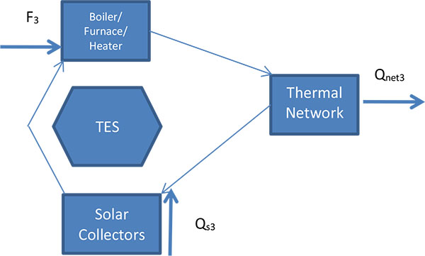 ), solar collectors and fossil fuel heater equipment both provide energy for the solar-assisted DE system. In this mode the TES is not active. The solar energy is transferred directly to the fossil fuel heater for supplemental heating. Mode 3 occurs when there is a heat demand while sunlight is available. This mode can occur throughout the year, but is less common in the summer when solar collectors receive more solar energy due to the longer days.
 |
Fig. (5) Operating Mode 3 for a DE system assisted by solar thermal and TES, showing flows of energy. |
In (Fig. 5), F3 and Qs3 are the energy supplied to the control volume by the fossil fuel heater and the solar collectors, respectively, and Qnet3 is the useful energy delivered in Mode 3. Q3 is the parameter introduced for Mode 3; from other side the annual fossil fuel consumption is known and fossil fuel energy used in Modes 2 and 3 are calculated in previous sections, thus Q3 is difference between annual consumption and summation of Q1 and Q2. This can be written as follows:
 |
(21) |
With equations (1) and (2), the following energy balances can be written for the DE system in Mode 3:
 |
(22) |
The quantity Qs3 can be expressed as:
 |
(23) |
where Qs is the total solar energy collected and Qin-TES is the solar energy input to the TES during the charging stage. The latter quantity has been examined in detail previously by Rezaie et al . [29Rezaie, B.; Reddy, B.V.; Rosen, M.A. Seasonal stratified thermal energy storage exergy analysis. Building Simulation Conference, Halifax, NS, CanadaMay 1-4, 2012, 30Rezaie, B.; Reddy, B.V.; Rosen, M.A. Exergy assessment of the use of thermal storage in a district energy system: Case study seasonal stratified thermal energy storage exergy analysis. Proc. INNOSTOCK 2012: 12th International Conference on Energy Storage, Lleida, Spain, May 16-18, 2012.].
Also, Q3 = F3 + Qs3 where F3 is the energy the fossil fuel heater inputs to the thermal network. Then:
 |
(24) |
Then energy efficiency for the Mode 3, ɳ3, can be written as:
 |
(25) |
An exergy balance for the Friedrichshafen thermal network in Mode 3 can be written by using equations (3) and (4) as:
 |
(26) |
Here, ExQnet3 of the exergy of Qnet3, hout and hin, sout, sin, from / to thermal network, T0 are already defined, and m3 is the mass of the circulating media passing through the thermal network during the operating period, which can be determined as follows:
 |
(27) |
where, as for Modes 1 and 2, ∆T is the temperature difference between inlet and outlet circulating media for the thermal network. Also, the exergy associated with the fuel energy F3, ExF3, can be expressed as:
 |
(28) |
and the exergy of Qs3, ExQs3, can be written as
 |
(29) |
The exergy efficiency of the solar assisted DE system for Mode 3 Ψ3 can be expressed as:
 |
(30) |
2.3. DE System Total Efficiency
To estimate the efficiency we assess the performance of the solar assisted DE system as a whole system, oprating in all modes. This approach is simplistic but, by generalizing conditions like ambient temperature over the year, loses some accuracy.
With the general approach, we consider the performance over an entire year. For simplicity, we assume that the system acts in a cyclic manner over a year, and that the system returns to its initial state after one year. A total quantity of solar energy (Qs) is supplied to the DE system, directly (Qs2) and through the TES (Qs3), and the fossil fuel heater operates to provide heat to the DE system by using a total amount of fuel (Fgas= F1 + F2 + F3). The total demand of the DE system is deducted by the network loss to determine the net heat demand (Qnet = Qnet1+ Qnet2+ Qnet3). (Fig. 6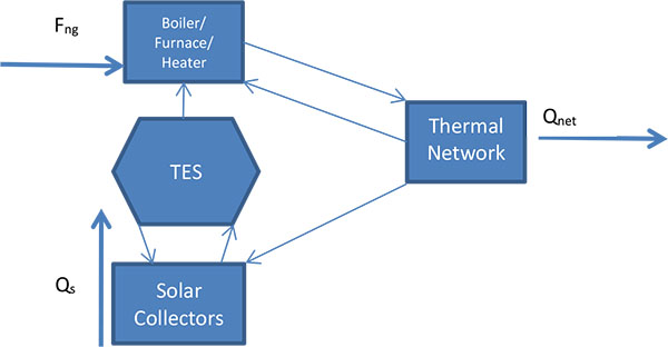 ) depicts the general thermal cycle, which combines various operating modes.
We consider a control volume the entire system in the thermodynamic analysis. Fng and Qs are the energy externally supplied to the control volume and Qnet is the annual useful energy delivered. Fng denotes the fuel energy entering the fossil fuel heater and Qs is the total solar energy collected by the solar panels. With equations (1) and (2), we can write following equations:
 |
Fig. (6) Simplified representation of the general performance of the DE system assisted by solar thermal and TES, showing possible flows of energy. |
 |
(31) |
 |
(32) |
By replacing equivalent amount for Qnet, Fng, and Qs from modes 1, 2, and 3 in above equation, the thermodynamic energy efficiency ɳ of the solar assisted DE system is expressed as follows:
 |
(33) |
where the parameters are already introduced. Since Qin-c= QS2, then values of all terms in equation (33) are known.
The exergy efficiency ψ of the solar assisted DE system can be expressed as:
 |
(34) |
Knowing ExQS2= Exin-c the terms in the above equation can be calculated.
3. CASE STUDY: FRIEDRICHSHAFEN DE SYSTEM
Efforts have been made in many countries and regions to increase the application of renewable energy, such as solar and wind energy, and to reduce fossil fuel use. For example, “Solarthermie2000”, the 4th programme of “Energy Research and Technology” by the Germany Federal government, has fostered significant progress in the development of second and third generation solar-assisted district heating plant in conjunction with seasonal thermal storage [39Mangold, D.; Schmidt, T.; Lottner, V. Seasonal thermal energy storage in Germany. Proc. Futurestock, 2003, ]. Seasonal thermal storage often utilizes thermal insulation with a low thermal conductivity to decrease thermal losses. Large scale, long term thermal storage is often more cost effective than small scale, short term TES [40Lottner, V.; Mangold, D. Status of seasonal thermal energy storage in Germany. Proc. TERRASTOCK, 2000, 1, 53-60.]. A large scale TES is included in the Friedrichshafen DE system.
Nuβbicker et al. [41Nußbicker, J.; Bauer, D.; Marx, R.; Heidemann, W.; Muller-Steinhagen, H. Monitoring results from German central solar heating plants with seasonal storage Proc. EFFSTOCK, June 14-17 2009.] note that the Friedrichshafen DE system has hot water thermal energy storage made of reinforced concrete with a volume of 12,000 m3. The first phase the Friedrichshafen DE system covered 280 apartments containing multi-family houses and a daycare, utilized solar collectors with an area of 2700 m2, and satisfied 24% of the total heat demand of the district heating system via solar energy. In the second phase, established in 2004, district heating was expanded to a second set of apartments comprising 110 units, which caused the addition of 1350 m2 of solar collectors to the system. Also, two gas condensing boilers, with capacities of 750 kW and 900 kW, were installed to allow the energy demand for district heating to be met if the combination of solar collectors and thermal storage was not adequate. The Friedrichshafen DE system consists of two natural gas boilers, a set of flat-panel solar thermal collectors, mostly on building roofs, a Central Solar Heating Plant with Seasonal Heat Storage (CSHPSS), several heat exchangers to allow the exchange of heat between the thermal network and the solar panels, the thermal network which distributes heat to consumers, pipes, pumps and valves. Water is the circulating thermal transport medium in the Friedrichshafen system and is also the heat storage medium. Externally supplied heat to the Friedrichshafen DE system is from boilers and solar collectors; and thermal network is the main consumer of heat. Nuβbicker et al. [41Nußbicker, J.; Bauer, D.; Marx, R.; Heidemann, W.; Muller-Steinhagen, H. Monitoring results from German central solar heating plants with seasonal storage Proc. EFFSTOCK, June 14-17 2009.] report the following data for the Friedrichshafen DE system:
- Return water temperature from network: 55.4°C.
- Measured annual heat loss of TES: 421 MWh.
- Storage efficiency: 60%.
- Annual solar yield of collectors: 1200 MWh.
- Annual solar heat input to district heating network: 803 MWh.
- Overall annual heat input into the district heating network: 3017 MWh.
- Annual heat delivery by gas bolilers: 2310 MWh.
- Solar fraction: 26%.
- Portion of heat loss of the district heating network for the 2nd residential area: 7.3%.
- Maximum temperature inside TES: 81°C (at top).
- Capacities of two gas boilers: 750 kW and 900 kW.
Also, Lottner and Mangold [40Lottner, V.; Mangold, D. Status of seasonal thermal energy storage in Germany. Proc. TERRASTOCK, 2000, 1, 53-60.] and Fisch and Kubler [42Fisch, N.; Kubler, R. Solar assisted district heating-status of the projects in Germany. Int. J. Sustain. Energy, 1997, 18(4), 259-270.] report the temperature of thermal network (T) to be 70°C. A typical efficiency of “gas fired condensing boilers,” which is taken to be representative here, is about 90% [43Harvey, D.L.D. A Handbook on Low-Energy Buildings and District-Energy Systems., 2006, , 44SEDBUK (Seasonal Efficiency of Domestic Boilers in the UK) Rating. http://www.homeheatingguide.co.uk/sedbuk-rating.html (Accessed 20 January 2017).].
The present authors apply several simplifying assumptions including the assumption, based on a similar thermal system reported by Zhai et al . [45Zhai, H.; Dai, Y.J.; Wu, J.Y.; Wang, R.Z. Energy and exergy analyses on a novel hybrid solar heating, cooling and power generation system for remote areas. Appl. Energy, 2009, 86, 1395-1404.], that heat loss in pipelines can be neglected.
(Fig. 7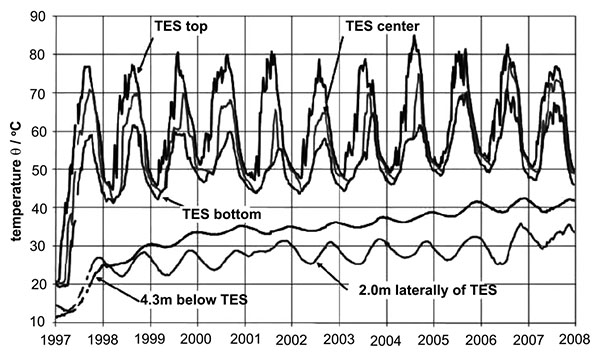 ) depicts the history of several relevant temperatures for the Friedrishchafen DE system since it commenced operation. Although the system generally follows an annual cycle, the temperature varies from year to year. In the winter the temperature reaches a minumum and in the late summer a maximum temperature is observed.
 |
Fig. (7) History of selected temperatures for the TES and surrounding soil for the Friedrichshafen DE system. |
Source: Nuβbicker et al . [41Nußbicker, J.; Bauer, D.; Marx, R.; Heidemann, W.; Muller-Steinhagen, H. Monitoring results from German central solar heating plants with seasonal storage Proc. EFFSTOCK, June 14-17 2009.], Printed by permission
For the present case, we consider the year 2006. TES temperatures for each month and season of this reference year are read from (Fig. 7), and are tabulated in (Table 1). The ambient air temperature, which is taken to be the reference environment temperature To, for the 12 months of 2006 is depicted in (Table 1) [46SEDBUK (Seasonal Efficiency of Domestic Boilers in the UK) Rating. http://www.homeheatingguide.co.uk/sedbuk-rating.html (Accessed 20 January 2017).].
The total energy loss of the TES during the year 2006 was reported as 421 MWh Nuβbicker et al . [41Nußbicker, J.; Bauer, D.; Marx, R.; Heidemann, W.; Muller-Steinhagen, H. Monitoring results from German central solar heating plants with seasonal storage Proc. EFFSTOCK, June 14-17 2009.]; this loss needs to be distributed into 12 months. The temperature difference between the TES and the soil at a depth of 4.3m under the TES is calculated for 12 months. The soil temperature be read from (Fig. 7) and tabulated in (Table 1). (Table 1) also contains the TES monthly energy loss. The distribution of generated solar energy, estimated by Rezaie et al . [24Rezaie, B.; Reddy, B.V.; Rosen, M.A. Role of thermal energy storage in district energy systems.Energy Storage., 2011, ], is also illustrated in (Table 1). Besides, the total temperature differences between the average TES (Tave) and the soil (Soil Temp.) over the 12 months is 388°C; the energy loss in each month is calculated by multiplying each monthly temperature difference by the ratio of 421/388.
The energy grade function R for natural gas is taken to be 0.913 throughout [32Rosen, M.A.; Le, M.N.; Dincer, I. Efficiency analysis of a cogeneration and district energy system. Appl. Therm. Eng., 2005, 25, 147-159.].
3.1. Performance of Operating Modes
3.1.1. Thermal Process Mode 1
In this mode, boilers are the only source of heating. Water does not circulate in the TES or solar collectors. Water with a temperature of 83°C flows into the thermal network, transfers heat to the thermal network, and returns from the thermal network outlet at 55.4°C to the boilers. The Friedrichshafen DE system operates in Mode 1 during November, December, January, and February, because the TES is discharged and the available solar energy is insufficient to satisfy the Friedrichshafen DE system’s demand. The performance of the Friedrichshafen DE system in Mode 1 is evaluated with Equations (5) to (11) and depicted in (Table 2).
3.1.2. Thermal Process Mode 2
In this mode, the TES operates with the boilers. Water in the TES is previously heated by surplus energy from the solar panels after feeding the DE system. This preheated water is discharged from the TES and enters the boilers when a significant demand for thermal energy exists. Mode 2 proceeds until the TES water temperature exceeds the thermal network temperature (55.4°C). The duration of Mode 2 is September and October. Energy and exergy parameters are evaluated with Equations (12) to (20) and listed in (Table 2).
3.1.3. Thermal Process Mode 3
During Mode 3, solar thermal collectors and boilers both provide energy for the Friedrichshafen DE system, and the TES does not operate. Water from the solar collectors at 81°C flows directly to the boilers. Mode 1 occurs throughout the year. The DE system performance in Mode 3 is evaluated with Equations (21) to (30) and described in (Table 2).
3.2. Total Efficiency
The total efficiency of the Friedrichshafen DE system can be estimated by using equations (33) and (34) for energy and exergy efficiencies. Energy efficiency of 87% and exergy efficiency of 27% are results of applying equations (33) and (34) on the Friedrichshafen DE system.
3.3. DISCUSSION
Energy and exergy efficiencies of the Friedrichshafen DE system in three different thermal process modes are tabulated beside the total Energy and exergy efficiencies of that DE system in (Table 3).
Operating Mode 1 is totally dependent on the natural gas as boilers are the only source of energy; this mode has the lowest energy and exergy efficiencies, 83% and 23% respectively, compared to the other modes. When solar collectors indirectly through the TES provide heat for the DE system in Mode 2 and, in this mode; the energy and exergy efficiencies boost up to 90% and 35% which is an improvement for the Friedrichshafen DE system relative to Mode 1. In Mode 3, solar energy directly assists the boilers and the energy and exergy efficiencies increase to 90% and 36% in compare with Mode 1 values. This comparison shows the positive impact of TES and solar panels in improvement of Friedrichshafen DE system.
The total energy and exergy efficiencies are driven with the concept of adding up the input and output energy in modes 1, 2, and 3, then to estimate the energy and exergy efficiencies during a typical year performance of Friedrichshafen DE system. The total energy and exergy efficiencies are also higher than the energy and exergy efficiencies of the DE system when is just working with the fossil fuels. This happens just because of applying solar collectors and TES in the thermal processes in Friedrichshafen DE system. Solar collectors and TES supply more efficient energy to the DE system, therefore the total energy and exergy efficiencies of the Friedrichshafen DE system increase.
The result of this study enforces the positive role of the TES in solar assisted DE system like the Friedrichshafen DE system.
CONCLUSION
Solar thermal technology and TES are two methods of modification of DE systems. Both are applied in the Friedrichshafen DE system to increase its performance. For determining the energy and exergy efficiencies of the Friedrichshafen DE system, it is divided into three thermal process modes. Each mode is analysed thermodynamically separately.
A comparison of the operating modes verifies that when Friedrichshafen DE system is working just with natural gas it has lower energy and exergy efficiencies. When solar collectors and TES assist the natural gas, the energy and exergy efficiencies are much higher (Table 3). Note that this comparison is theoretical to demonstrate positive impact of solar energy and TES on the performance of the Friedrichshafen DE system in terms of the improvements to the energy and exergy efficiencies.
The actual performance of the Friedrichshafen DE system is a combination of three modes. In other words, the combination of the performances of the three thermal cycle modes defines the annual performance of the Friedrichshafen DE system. In the annual performance of Friedrichshafen DE system the total energy efficiency is 87% while the exergy efficiency in a typical year is 27%. These values are based on the energy and exergy efficiencies of the three thermal process modes of the Friedrichshafen DE system (Table 3).
NOMENCLATURE
| Cp | = Specific heat at constant pressure, kJ/kg °C |
| ExF1 | = Exergy supply by fossil fuel heater in Mode 1, kJ |
| ExF2 | = Exergy supply by fossil fuel heater in Mode 2, kJ |
| ExF3 | = Exergy supply by fossil fuel heater in Mode 3, kJ |
| ExFng | = Energy supply by fossil fuel heater, kJ |
| ExQnet1 | = Net exergy demand in Mode 1, kJ |
| ExQnet | = Net exergy demand, kJ |
| ExQnet2 | = Net exergy demand in Mode 2, kJ |
| ExQnet3 | = Net exergy demand in Mode 3, kJ |
| ExQs2 | = Exergy supply by solar energy in Mode 2, kJ |
| ExQs3 | = Exergy supply by solar energy in Mode 3, kJ |
| ExQs | = Exergy supply by solar energy, kJ |
| F1 | = Energy supply by fossil fuel heater in Mode 1, kJ |
| F2 | = Energy supply by fossil fuel heater in Mode 2, kJ |
| F3 | = Energy supply by fossil fuel heater in Mode 3, kJ |
| Fng | = Energy supply by fossil fuel heater, kJ |
| hin | = Inlet specific enthalpy, kJ/kg |
| hout | = Outlet specific enthalpy, kJ/kg |
| m | = Mass of water transferring energy, kg |
| m1 | = Mass of water transferring energy in Mode 1, kg |
| m2 | = Mass of water transferring energy in Mode 2, kg |
| m3 | = Mass of water transferring energy in Mode 3, kg |
| ɳ1 | = Energy efficiency in Mode 1 |
| ɳ2 | = Energy efficiency in Mode 2 |
| ɳ3 | = Energy efficiency in Mode 3 |
| ɳ | = Energy efficiency by general approach |
| Q1 | = Energy supply in Mode 1, kJ |
| Q2 | = Energy supply in Mode 2, kJ |
| Q3 | = Energy supply in Mode 3, kJ |
| Qnet | = Net energy demand by Friedrichshafen DE system, kJ |
| Qnet1 | = Net energy demand by Friedrichshafen DE system in Mode 1, kJ |
| Qnet2 | = Net energy demand by Friedrichshafen DE system in Mode 2, kJ |
| Qnet3 | = Net energy demand by Friedrichshafen DE system in Mode 3, kJ |
| Qrec | = Energy recovered from TES, kJ |
| Qs | = Solar energy supply, kJ |
| Qs2 | = Solar energy supply in Mode 2, kJ |
| Qs3 | = Solar energy supply in Mode 3, kJ |
| R | = Energy grade function |
| sin | = Inlet specific entropy, kJ/kg K |
| sout | = Outlet specific entropy, kJ/kg K |
| T0 | = Ambient temperature, °C |
| ψ1 | = Exergy efficiency in Mode 1 |
| ψ2 | = Exergy efficiency in Mode 2 |
| ψ3 | = Exergy efficiency in Mode 3 |
| ψ | = Exergy efficiency by general approach |
CONSENT FOR PUBLICATION
Not applicable.
CONFLICT OF INTEREST
The authors declare no conflict of interest, financial or otherwise.
ACKNOWLEDGEMENTS
Financial support was provided by the Natural Sciences and Engineering Research Council of Canada, and is gratefully acknowledged.
REFERENCES
| [1] | Robins, J. The new good life: Living better than ever in an age of less., 2010, |
| [2] | Rosen, M.A. Combatting global warming via non-fossil fuel energy options. Int. J. Glob. Warm., 2009, 1(1-3), 2-28. |
| [3] | Schmidt, D. Low exergy systems for high-performance buildings and communities. Energy Build., 2009, 41(3), 331-336. |
| [4] | Moran, M.J. Availability analysis is a guide to efficient energy use. Corrected Edition., 1989, |
| [5] | Annex 49. Energy conservation in buildings and community systems-Low exergy systems for high-performance buildings and communities, http://www.annex49.com/background.html (Accessed 5 March 2018). |
| [6] | Bloomquist, R.G. Geothermal space heating. Geoth, 2003, 32(4-6), 513-526. |
| [7] | Ozenger, L.; Hepbasli, A.; Dincer, I. Energy and exergy analysis of geothermal district heating system: An application. Build. Environ., 2005, 40(10), 1309-1322. |
| [8] | Faninger, G. Combined solar biomass district heating in Austria. Sol. Energy, 2000, 69, 425-435. |
| [9] | Lottner, V.; Schulz, M.E.; Hahne, E. Solar assisted district heating plants: status of the German programme solarthermie-2000. Sol. Energy, 2000, 69, 449-459. |
| [10] | Hepbasli, A.; Canakci, C. Geothermal district heating applications in Turkey: A case study of Izmir-Balcova. Energy Convers. Manage., 2003, 44(8), 1285-1301. |
| [11] | Rezaie, B.; Rosen, M.A. District heating and cooling: Review of technology and potential enhancements. Appl. Energy, 2012, 93, 2-10. |
| [12] | Lake, A.; Rezaie, B.; Beyerlein, S. Review of district heating and cooling systems for a sustainable future. Renew. Sustain. Energy Rev., 2017, 67, 417-425. |
| [13] | Patil, A.; Ajah, A.; Herder, P. Recycling industrial waste heat for sustainable district heating: A multi-actor perspective. Int. J. Environ. Technol. Manag., 2009, 10, 412-426. |
| [14] | Casten, T.R.; Ayers, R.U. Recycling energy: Growing income while mitigating climate change, Report, Recycled Energy Development, 2017, |
| [15] | Cogeneration or combined heat and power., 2003, |
| [16] | Lund, H.; Moller, B.; Mathiesen, B.V.; Dyrelund, A. The role of district heating in future renewable energy systems. Energ, 2003, 32, 1381-1390. |
| [17] | Li, Y.; Liu, G.; Liu, X.; Liao, S. Thermodynamic multi-objective optimization of a solar-dish Brayton system based on maximum power output, thermal efficiency and ecological performance. Renew. Energy, 2016, 95, 465-473. |
| [18] | Lemale, J.; Jaudin, F. La geothermie, une energie d’avenir, une realite en Ile de France., 1999, Geothermal heating, an energy of the future, a reality in Ile-de-France |
| [19] | Marinova, M.; Beaudry, C.; Taoussi, A.; Trepanier, M.; Paris, J. Economic assessment of rural district heating by bio-steam supplied by a paper mill in Canada. Bull. Sci. Technol. Soc., 2008, 28(2), 159-173. |
| [20] | Gebremedhin, A. The role of a paper mill in a merged district heating system. Appl. Therm. Eng., 2003, 23, 769-778. |
| [21] | Pavlas, M.; Stehlik, P.; Oral, J.; Sikula, J. Integrating renewable sources of energy into an existing combined heat and power system. Energ, 2006, 31, 2499-2511. |
| [22] | Soltani, R.; Dincer, I.; Rosen, M.A. Thermodynamic analysis and performance assessment of an integrated heat pump system for district heating applications. Appl. Therm. Eng., 2015, 89, 833-842. |
| [23] | Andrepont, J.S. Maximize district energy value by leveraging technology options. District Energy, 2006, 92(4), 40-41. |
| [24] | Rezaie, B.; Reddy, B.V.; Rosen, M.A. Role of thermal energy storage in district energy systems.Energy Storage., 2011, |
| [25] | Kharseh, M.; Nordell, B. Sustainable heating and cooling systems for agriculture. Int. J. Energy Res., 2011, 35, 415-422. |
| [26] | Rad, F.M.; Fung, A.S.; Rosen, M.A. An integrated model for designing a solar community heating system with borehole thermal storage. Energy Sustain. Dev., 2017, 36C, 6-15. |
| [27] | Sapińska-Śliwa, A.; Rosen, M.A.; Gonet, A.; Śliwa, T. Deep borehole heat exchangers: a conceptual review. Int. J. Air-Cond. Ref., 2016, 24(1), 1630001. |
| [28] | Jiaqiang, E.; Zuo, W.; Liu, X.; Peng, Q.; Deng, Y.; Zhu, H. Effects of inlet pressure on wall temperature and exergy efficiency of the micro-cylindrical combustor with a step. Appl. Energy, 2016, 175, 337-345. |
| [29] | Rezaie, B.; Reddy, B.V.; Rosen, M.A. Seasonal stratified thermal energy storage exergy analysis. Building Simulation Conference, Halifax, NS, CanadaMay 1-4, 2012 |
| [30] | Rezaie, B.; Reddy, B.V.; Rosen, M.A. Exergy assessment of the use of thermal storage in a district energy system: Case study seasonal stratified thermal energy storage exergy analysis. Proc. INNOSTOCK 2012: 12th International Conference on Energy Storage, Lleida, Spain, May 16-18, 2012. |
| [31] | Rosen, M.A.; Dincer, I. Exergoeconomic analysis of power plants operating on various fuels. Appl. Therm. Sci, 2003, 23, 643-658. |
| [32] | Rosen, M.A.; Le, M.N.; Dincer, I. Efficiency analysis of a cogeneration and district energy system. Appl. Therm. Eng., 2005, 25, 147-159. |
| [33] | Rosen, M.A.; Dincer, I.; Kanoglu, M. Role of exergy in increasing efficiency and sustainability and reducing environmental impact. Energ. Pol., 2008, 36, 128-137. |
| [34] | Dincer, I.; Al-Muslim, H. Thermodynamic analysis of reheat cycle steam power plants. Int. J. Energy Res., 2005, 25, 727-739. |
| [35] | Compton, M.; Rezaie, B. Enviro-exergy sustainability analysis of boiler evolution in district energy system. Energy, 2017, 119, 257-265. |
| [36] | Rezaie, B.; Reddy, B.V.; Rosen, M.A. Exergy analysis of thermal energy storage in a district energy application. Renew. Energy, 2015, 74, 848-854. |
| [37] | Dincer, I.; Rosen, M.A. Thermal energy storage: Systems and applications., (2nd ed. ), 2011, |
| [38] | Dincer, I.; Rosen, M.A. Exergy: Energy, environment and sustainable development., (2nd ed. ), 2013, |
| [39] | Mangold, D.; Schmidt, T.; Lottner, V. Seasonal thermal energy storage in Germany. Proc. Futurestock, 2003, |
| [40] | Lottner, V.; Mangold, D. Status of seasonal thermal energy storage in Germany. Proc. TERRASTOCK, 2000, 1, 53-60. |
| [41] | Nußbicker, J.; Bauer, D.; Marx, R.; Heidemann, W.; Muller-Steinhagen, H. Monitoring results from German central solar heating plants with seasonal storage Proc. EFFSTOCK, June 14-17 2009. |
| [42] | Fisch, N.; Kubler, R. Solar assisted district heating-status of the projects in Germany. Int. J. Sustain. Energy, 1997, 18(4), 259-270. |
| [43] | Harvey, D.L.D. A Handbook on Low-Energy Buildings and District-Energy Systems., 2006, |
| [44] | SEDBUK (Seasonal Efficiency of Domestic Boilers in the UK) Rating. http://www.homeheatingguide.co.uk/sedbuk-rating.html (Accessed 20 January 2017). |
| [45] | Zhai, H.; Dai, Y.J.; Wu, J.Y.; Wang, R.Z. Energy and exergy analyses on a novel hybrid solar heating, cooling and power generation system for remote areas. Appl. Energy, 2009, 86, 1395-1404. |
| [46] | Historical Weather: Friedrichshafen. www.tutiempo.net/en/Climate/Friedrichshafen/109350.html. (Accessed 20 January, 2017). |