- Home
- About Journals
-
Information for Authors/ReviewersEditorial Policies
Publication Fee
Publication Cycle - Process Flowchart
Online Manuscript Submission and Tracking System
Publishing Ethics and Rectitude
Authorship
Author Benefits
Reviewer Guidelines
Guest Editor Guidelines
Peer Review Workflow
Quick Track Option
Copyediting Services
Bentham Open Membership
Bentham Open Advisory Board
Archiving Policies
Fabricating and Stating False Information
Post Publication Discussions and Corrections
Editorial Management
Advertise With Us
Funding Agencies
Rate List
Kudos
General FAQs
Special Fee Waivers and Discounts
- Contact
- Help
- About Us
- Search


The Open Fuels & Energy Science Journal
(Discontinued)
ISSN: 1876-973X ― Volume 11, 2018
On the Influence of the Slot Orifice in Diesel Common Rail Nozzle
Giancarlo Chiatti, Ornella Chiavola, Fulvio Palmieri*, Roberto Pompei
Abstract
Background:
The paper deals with a diesel common rail nozzle in which a novel orifice layout is implemented.
Objective:
Its influence on the nozzle mechanical-hydraulic behavior and on the spray shape transient development is experimentally investigated.
Methods:
In the research, a solenoid injector for light duty diesel engines is equipped with the novel nozzle prototype and tested. The prototype layout is described, pointing out the features of the nozzle orifices, in which a Slot cross-section is adopted; the investigation is accomplished extending the hydraulic tests and the spray visualizations to a reference nozzle with standard holes. The influence of the hole layout on the mechanical-hydraulic behavior of the nozzle is assessed by experimental analysis based on the rate of injection measurement, in comparison with the reference nozzle. Once the hydraulic behavior of the novel nozzle has been characterized in terms of mass flow rate, the slot influence on the spray shape is assessed analyzing the macroscopic features such as the penetration distance and the spray angle, in non evaporative conditions. The study is carried out under transient injection conditions, for different injection pressures, up to 1400 bar.
Results:
The results on spray characteristics also provide reference information to set up spray models suited to take the Slot orifice into account.
Article Information

Identifiers and Pagination:
Year: 2018Volume: 11
First Page: 55
Last Page: 69
Publisher Id: TOEFJ-11-55
DOI: 10.2174/1876973X01811010055
Article History:
Received Date: 05/12/2017Revision Received Date: 23/03/2018
Acceptance Date: 03/04/2018
Electronic publication date: 30/04/2018
Collection year: 2018
open-access license: This is an open access article distributed under the terms of the Creative Commons Attribution 4.0 International Public License (CC-BY 4.0), a copy of which is available at: https://creativecommons.org/licenses/by/4.0/legalcode. This license permits unrestricted use, distribution, and reproduction in any medium, provided the original author and source are credited.
* Address correspondence to this author at the Department of Engineering, Undiversità degli Studi Roma TRE, Rome, Italy, Tel: +390657333493; E-mail: fulvio.palmieri@uniroma3.it
All authors contributed equally to the work.
| Open Peer Review Details | |||
|---|---|---|---|
| Manuscript submitted on 05-12-2017 |
Original Manuscript | On the Influence of the Slot Orifice in Diesel Common Rail Nozzle | |
1. INTRODUCTION
The engine performance, the efficiency and the impact on the environment are progressively improved through multidisciplinary research and development activities; in a simple but effective standpoint, two main research paths can be outlined in the engine development. The former is devoted to improve the after-treatment technology; the latter is oriented towards the control of combustion process with enhanced accuracy.
Focusing the attention on the latter research path, fuel injection is found among those factors that mostly influence the combustion; fuel injection is also regarded as one of the most complex processes in diesel engines. Going more in-depth on the fuel injection topic, alongside the wide spectrum of possibilities (e.g. control of injection strategy, fuel properties, rate of injection shaping), a direct way to influence diesel combustion and pollutant formation is based on straight actions on the injector nozzle geometry. Such a field of research mostly relies on miniaturizing the nozzle orifices, but also on devising different geometries for the nozzle orifice that may usefully affect the nozzle flow and the spray characteristics. The perspective to seek progresses through nozzle hole design is interesting, since they may allow to improve the nozzle performance [1Chiatti, G.; Chiavola, O.; Palmieri, F. Diesel nozzle flow investigation in non-radial multi hole geometry. ASME 2014 Internal Combustion Engine Division Fall Technical Conference, ICEF 2014
[http://dx.doi.org/10.1115/ICEF2014-5556] , 2Chiatti, G.; Chiavola, O.; Palmieri, F. Flow features in reduced dwell time diesel injector. SAE Tech. Pap., 2008.], the spray abnormalities [3Chiatti, G.; Chiavola, O.; Frezzolini, P.; Palmieri, F. On the link between diesel spray asymmetry and off-axis needle displacement. Appl. Sci. (Basel), 2017, 7(4), 375.
[http://dx.doi.org/10.3390/app7040375] ], and the emission control in a simple and cost-efficient way.
In the literature, many studies investigated the influence of geometrical factors on the spray [4Payri, R.; Viera, J.P.; Gopalakrishnan, V.; Szymkowicz, P.G. The effect of nozzle geometry over ignition delay and flame lift-off of reacting direct-injection sprays for three different fuels. Fuel, 2017, 199, 76-90.
[http://dx.doi.org/10.1016/j.fuel.2017.02.075] -9Som, S.; Ramirez, A.I.; Longman, D.E.; Aggarwal, S.K. Effect of nozzle orifice geometry on spray, combustion, and emission characteristics under diesel engine conditions. Fuel, 2011, 90(3), 1267-1276.
[http://dx.doi.org/10.1016/j.fuel.2010.10.048] ]. Some researchers, which consider the cross-section shape of the hole, have investigated elliptic liquid jets at low flow speed, when injected in gaseous environments [10Amini, G.; Dolatabadi, A. Breakup of liquid jets emerging from elliptic orifices. 2011 Proceedings of the ASME Turbo Expo, 2 (PARTS A AND B), 417-414.
[http://dx.doi.org/10.1115/GT2011-45390] -12Kasyap, T.V.; Sivakumar, D.; Raghunandan, B.N. Flow and breakup characteristics of elliptical liquid jets. Int. J. Multiph. Flow, 2009, 35(1), 8-19.
[http://dx.doi.org/10.1016/j.ijmultiphaseflow.2008.09.002] ]. These works found an unusual behavior of the jets, which is known as “switching axes”. The researchers observed that the liquid jet cross-section changes shape downstream, switching repeatedly the minor and the major axis. The jet spread in the minor axis section becomes greater than the major axis section. This means that the elliptic jet turns circular, and then elliptic again, but in the reverse configuration. This behavior occurs downstream over and over again and these studies explained this effect relating two opposite forces balancing together, namely the surface tension, which contrasts the jet breakup, and the inertial force, which tries to expand and fragment the jet. The resulting asymmetric structure of the flow and its natural tendency to reach the minimum energy configuration are thought to be the cause of such a behavior.
Some researchers started considering the modification of the standard orifice layout as a way to alter the diesel spray formation [13Yunyi, G.; Changwen, L.; Yezhou, H.; Zhijun, P. An experimental study on droplet size characteristics and air entrainment of elliptic sprays. SAE Tech. Pap, 1998.
[http://dx.doi.org/10.4271/982546] ]. Jacobson [14Jacobsson, L.; Chomiak, J. Injection orifice shape: Effects on combustion and emission formation in diesel engines. SAE Tech. Pap, 1997.
[http://dx.doi.org/10.4271/972964] ] first achieved experimental studies testing elliptical nozzle holes in a single cylinder engine and in a constant-volume combustion chamber, finding substantial impact on NOX emission. At almost all loads and speeds, elliptical holes showed lower NOX emissions than the circular ones. Under some working conditions, elliptical holes even revealed lower particulate and HC emissions. A further study [15Jacobsson, L.; Winklhofer, E.; Chomiak, J. Injection orifice shape: Effects on spray characteristics and heat-release rate in a large-size single-cylinder diesel engine. SAE Tech Pap., 1999.] was performed on a three-liter single-cylinder engine with optical access. It was evidenced that the spray width in the minor axis plane of the elliptical hole increased twice as fast as that of the circular one. The spray angle in the major axis plane of the elliptical cross-section was smaller than that in the minor axis plane, but still larger than that of the circular one. The main differences were observed at low-pressure injection conditions (300 bar). The work reported in [16Matsson, A.; Jacobsson, L.; Andersson, S. The effect of elliptical nozzle holes on combustion and emission formation in a heavy duty diesel engine. SAE Tech. Pap., 2000.] has indicated significant improvements in fuel consumption/NOX emission tradeoff at several loads and speeds, as a consequence of the use of an elliptical shape for the nozzle hole.
The works reported above analyzed the effects of elliptical orifices on the spray and combustion process, but, as evidenced in [17Molina, S.; Salvador, F.J.; Carreres, M.; Jaramillo, D. A computational investigation on the influence of the use of elliptical orifices on the inner nozzle flow and cavitation development in diesel injector nozzles. Energy Convers. Manage., 2014, 79, 114-127.
[http://dx.doi.org/10.1016/j.enconman.2013.12.015] ], the nozzle was treated as a “black box”. In the effort to link the internal flow pattern of the nozzle to the shape of the spray (comparing circular and elliptical nozzle holes), Hong et al. [18Hong, J.G.; Kun, W.S.; Kim, R.; Lee, C.W. Effect of cavitation in circular nozzle and elliptical nozzles on the spray characteristic. Spray., 2010, 20(10), 887-886.
[http://dx.doi.org/10.1615/AtomizSpr.v20.i10.40] ] used transparent acrylic nozzle models, equipped with circular (3 mm diameter) and elliptical orifices having the same geometrical flow area; the authors reported a lower discharge coefficient for the elliptical nozzles and a lower discharge coefficient than that of the circular nozzle at the same Reynolds number.
Two last contributions reported in the literature are devoted to the study of the flow pattern within the nozzle, by 3D-CFD modeling. In [19Chiatti, G.; Palmieri, F. Hole cross section shape influence on diesel nozzle flow. SAE Tech. Pap., 2013.], the Slot (or oval) orifice shape has been considered; CFD investigations, based on RANS equations with k-epsilon closure, have been devoted to characterize the internal nozzle flow. Cavitation behavior has been simulated through a mechanical approach, based on Rayleigh-Plesset equation for bubble growth modeling [19Chiatti, G.; Palmieri, F. Hole cross section shape influence on diesel nozzle flow. SAE Tech. Pap., 2013.]. As the non-circular shape gives different options to the major-axis orientation in respect to the injector itself, these possibilities have been reasonably summarized in three layouts (“flat”, “inclined” and “vertical”). Depending on the case, different flow structures in the orifice are produced. In case of “flat” layout, relatively strong counter rotating and symmetric eddies are generated within the hole. The investigations have shown that the hole cross section shape has a tangible effect on the nozzle flow; the influences cover all the factors having a recognized role in the spray formation (cavitation, velocity vector field at orifice exit, turbulence kinetic energy). In [17Molina, S.; Salvador, F.J.; Carreres, M.; Jaramillo, D. A computational investigation on the influence of the use of elliptical orifices on the inner nozzle flow and cavitation development in diesel injector nozzles. Energy Convers. Manage., 2014, 79, 114-127.
[http://dx.doi.org/10.1016/j.enconman.2013.12.015] ] the potential of using elliptical nozzle holes has been evaluated, also there comparing the results of four different configurations of elliptical nozzles (two flow areas and two orientations of the ellipse) with a standard circular nozzle hole. In [17Molina, S.; Salvador, F.J.; Carreres, M.; Jaramillo, D. A computational investigation on the influence of the use of elliptical orifices on the inner nozzle flow and cavitation development in diesel injector nozzles. Energy Convers. Manage., 2014, 79, 114-127.
[http://dx.doi.org/10.1016/j.enconman.2013.12.015] ] the modeling approach has been based on RANS equations with RNG k-epsilon closure, whereas cavitation modeling has been treated in the frame of a Homogeneous Equilibrium Model, with barotropic equation. The comparison has been made in terms of mass flow, momentum flux and the non-dimensional parameters discharge coefficient (CD), area coefficient (CA) and velocity coefficient (CV). The major axis horizontally oriented elliptical nozzles were characterized by higher discharge coefficient than the vertically oriented ones, while the circular nozzles were found at intermediate values. The authors also inferred that in the mixing process (which was not studied) a better quality is presupposed for the major axis horizontally oriented nozzles whereas a worse quality is expected for the vertically oriented ones.
In the current paper, a nozzle prototype equipped with Slot orifices is studied experimentally, in comparison with a reference nozzle with standard circular holes. The current work is focused on the Slot geometry, which combines two different peculiarities. On the one hand, it makes the production process easier compared to the elliptical geometry. The slot can be manufactured using the standard circular electrode of micro-electro-discharge machines. Indeed, the Slot shape is obtained by an additional electrode translation, normally to the drilling axis. On the other hand, the similarity between Slot and elliptic shapes could produce comparable flow pattern within the nozzle and, thus, similar effects on the spray.
As a first step, the mechanical-hydraulic behavior of the nozzles is assessed and characterized; then the focus is moved to the macroscopic features of the fuel spray; the investigation is based on backlit imaging under non-igniting and non-evaporative conditions. Once processed, the images were used to characterize the spray plumes; the effect of injection pressure on spray development was also investigated. In the following sections, the details of materials, methods and test conditions are reported.
2. MATERIALS AND METHODS
2.1. Tested Nozzle Prototypes and Orifice Shapes
Two identical blank nozzles have been processed by EDM (Electro Discharge Machining), obtaining two different orifice geometries; for the sake of brevity, they are called “Round” and “Slot”.
The two nozzles were designed with the aim of making comparisons at the same conditions, namely the same fuel amount per injection shot and the same opening/closing time of the needle. This condition is verified and discussed in the results section by analyzing the mechanical hydraulic behavior of the nozzle.
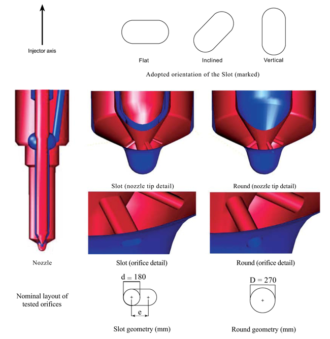 |
Fig. (1) Cross-sections of the investigated nozzle orifices. |
The two nozzles are multi-hole type (4-hole); concerning the former, it is based on a cylindrical standard hole and its simple layout is assumed as the reference case in the current investigation. In the latter layout, the slot cross section is implemented. Such a shape is realized in the attempt to achieve the same nominal geometrical flow area of the circular case. Dealing with non-circular holes a further concern is introduced, due to the freedom to orient the cross section in respect to the injector axis. This concern has been addressed in advance, on the basis of 3D-CFD nozzle flow simulations, whose results were collected and published in [19Chiatti, G.; Palmieri, F. Hole cross section shape influence on diesel nozzle flow. SAE Tech. Pap., 2013.]. The adopted configuration and the details of the tested nozzles are shown in Fig. (1 ), where the major axis of the section is normal to the injector axis.
According to Fig. (1), the chosen Slot cross section is formally related to the circular one by the following equations (1-4), which are directly derived from the adopted section geometries. Table 1 summarizes the relevant nominal dimensions of tested nozzle holes.
 |
(1) |
 |
(2) |
 |
(3) |
 |
(4) |

After drilling, the two nozzles have been hydro-ground. In order to avoid uncontrolled alterations of the Slot shape, the process has been limited admitting no more than 3% flow rate increase during steady hydro-grinding conditions. Hence, on the Round nozzle, the hydro-grinding was made up to reach the same flow rate of the Slot at the same steady flow conditions. In the experiments, the two prototype nozzles have been fitted, in turn, to the same injector body of a second generation common rail system.
2.2. Test Bed Set-Up
The investigation was carried out on the injection system test bed at Engineering Department of Roma TRE University. The set-up includes a complete common rail injection system (high-pressure pump, rail and solenoid injector), an auxiliary system for handling and temperature control of the injection fluid (ISO 4113 compliant oil), a long-tube device for ROI measurement and an optical diagnostic system for the fuel spray.
The ROI measure is based on the well-known Bosch Tube system [20Bosch, W. The fuel rate indicator: A new measuring instrument for display of the characteristics of individual injection. SAE Tech. Pap, 1966.
[http://dx.doi.org/10.4271/660749] ], in which the pressure wave is measured by means of a piezo-resistive pressure sensor (4067-type by Kistler, Winterthur, Switzerland). The same sensor is used to measure the pressure signal at injector inlet. ROI trends are obtained by averaging 256 injection shots. Injected quantities are gravimetrically measured by considering 1280 injection shots.
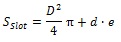
The spray visualization technique here adopted is backlit-imaging, based on the use of a DBI (Diffused Back Illumination) system, synchronized with the energizing signal of the injector solenoid valve. With high accuracy in time, an electronic controller implemented in the TB-ECU (Test Bed-Electronic Control Unit) is used to position the strobe-light emission in respect to the solenoid energizing signal. The sketch of the system is shown in Fig. (3 ), while the technical characteristics of the backlighting and digital imaging system are reported in Table (2). The injection of fuel takes place in a closed chamber, under non-evaporative conditions. The chamber is quiescent, operated with air (7 bar) at room temperature (25°C).
In the current investigation, the spray behavior is analyzed visualizing the shadowgraphs on two distinct planes, both containing the axis of the nozzle orifice (y-Axis) and orthogonal to each other, as shown in Fig. (2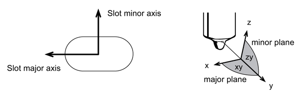 ); for the sake of simplicity, the plane also containing the minor axis of the Slot (z-Axis) is called “minor plane”, while the other one, containing the major axis of the Slot (x-Axis), hole is called “major plane”.
 |
Fig. (2) Reference axes on the slot section (left); planes of spray visualization (right). |
 |
Fig. (3) Sketch of the spray visualization system. |
The visualization process operates as follows. The low pressure fuel handling system feeds the main pump at fixed pressure and controls the fluid temperature to the level set for the tests. The main drive is started, operating the high pressure pump at 900 rpm and maintaining the pressure in the rail under closed-loop control of pressure regulator. The electronic controller sends the excitation signal to the injector. After a certain delay time ΔT, the TB-ECU sends the driving signal of the strobe lamp, which emits light for a fixed time period (50 ns). Such a fast flash “freezes” the development of the spray at a well-defined instant after the start of the solenoid excitation signal, with high accuracy; the system is able to analyze the evolution in time of a periodic event by building a succession of images obtained from multiple events by increasing, step by step, the delay time ΔT. In the present investigation, the uncertainty introduced on the time axis is bounded within 0.06 μs. Such a value is here regarded as negligible in comparison to the time scale (tenths of millisecond) of fuel injection process. Due to the occurrence of cyclic dispersion, the visualizations are repeated for each delay time at which the evolution of the spray is frozen, until the ± 5% accuracy in penetration distance and spray angle is achieved. As highlighted by relevant contributions in the field [21Kostas, J.; Honnery, D.; Soria, J. Time resolved measurements of the initial stages of fuel spray penetration. Fuel, 2009, 88(11), 2225-2237.
[http://dx.doi.org/10.1016/j.fuel.2009.05.013] , 22Eagle, E.W.; Morris, S.B.; Wooldridge, M.S. High-speed imaging of transient diesel spray behavior during high pressure injection of a multi-hole fuel injector. Fuel, 2014, 116, 299-309.
[http://dx.doi.org/10.1016/j.fuel.2013.07.120] ], cyclic dispersion is always encountered when the time evolution of the main macroscopic spray parameters are investigated (penetration, velocity of the spray-tip and opening angle of the spray); the dispersion of these parameters has been highlighted by cameras with very high frame-rate (e.g. 100.000 fps), able to record the time evolution of each single injection event. Surely the opportunity to study the evolution of a single event remains a key-factor in the spray research field, but then it should be noted that, due to the cyclic dispersion, it is necessary to repeat the analysis on more events to determine the average effective values that represent the spray behavior. Thus, for the purposes of the current study, the use of the strobe-technique is considered appropriate. Moreover, in the current framework, the strobe technique has some advantages over the high speed video technique. In fact, as a large number of frames per second is not managed, the use of very high resolution Active Pixel Sensors (APS) is possible (e.g. full-frame 24X36mm CMOS sensors - 36.2 megapixels) that produces high quality images.
2.3. Image Processing
The sprays from the two orifices under investigation were characterized in terms of the spray-tip penetration distance (i.e. the maximum penetration distance of the spray) and the cone angle of the spray, as a function of injection pressure. All the tested cases took place at the same chamber density. The raw images, once acquired, are post-processed in a self-developed code. All images undergo a common process, aimed at extracting the contour of the sprays. The procedure provides for the selection of the field of interest of the image, the gray scale conversion, the background image subtraction and the operation of thresholding to isolate the spray region and its boundary. Once the spray contour is isolated, additional steps allow obtaining the jet penetration and the spray angle. The gray-threshold value here adopted is 10/255, where 0 is black and 255 is white. Fig. (4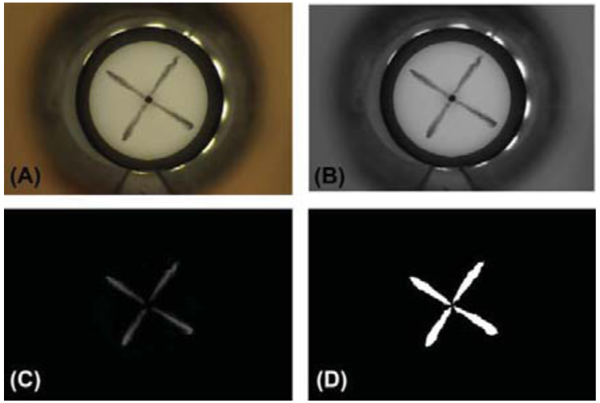 ) shows a sample of the image post processing.
 |
Fig. (4) Image post-processing; raw image (A); gray scale conversion (B); background subtraction (C); spray region extraction (D). |
2.4. Spray Shape Characterization
The spray shape is characterized by spray penetration and spray angle. The spray penetration is obtained by measuring the distance of the extreme point of the jet boundary from the hole exit section. The trend over time of the jet penetration is determined on the basis of the temporal spacing between one image acquisition and the other, which was set equal to 25 μs.
The spray angle is calculated according to what reported in the literature by [23Desantes, J.M.; Payri, R.; Salvador, F.J.; Gil, A. Development and validation of a theoretical model for diesel spray penetration. Fuel, 2006, 85(7-8), 910-917.
[http://dx.doi.org/10.1016/j.fuel.2005.10.023] , 24Shao, J.; Yan, Y. Digital imaging based measurement of diesel spray characteristics. IEEE Trans. Instrum. Meas., 2008, 57(9), 2067-2073.]. After the thresholding operation, in each frame, the spray region area is calculated. The spray angle is defined as the angle of the isosceles triangle having as the value of the height the jet penetration. The opening angle was also evaluated for fractions of the spray penetration, with the aim of obtaining information on the radial development of the jet along the direction of penetration. As previously mentioned the tested prototypes are multihole type, with four holes; thus, the visualizations were conducted isolating the attention on just one of the four sprays.
2.5. Test Cases
The analysis of the characteristics of the sprays has been performed considering three different injection conditions, as reported in Table 3.

3. RESULTS
3.1. Mechanical-Hydraulic Behavior
The investigation on the spray development was preceded by the characterization of the mechanical-hydraulic behavior of the two nozzles, using the anechoic tube to reconstruct the Rate of Injection (ROI) trends over time.
The amount of injected fuel has been shown to be independent of the nozzle type, for all the pressure levels considered (Table 4); the maximum deviation is observed in the cases at 1000 bar, and it does not exceed 2.5%.

Once it has been found that the tested nozzles are able to inject the same fuel quantity with injections of the same duration, the ROI trends are analyzed. The adopted Slot does not alter the mechanical-hydraulic behavior of the nozzle; in fact the start, the end and the duration of the injection do not depend on the nozzle type.
At the lower pressure level, ROI trends are equivalent, as shown in Fig. (5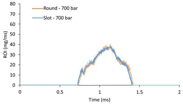 ). At higher pressures (Figs. 6
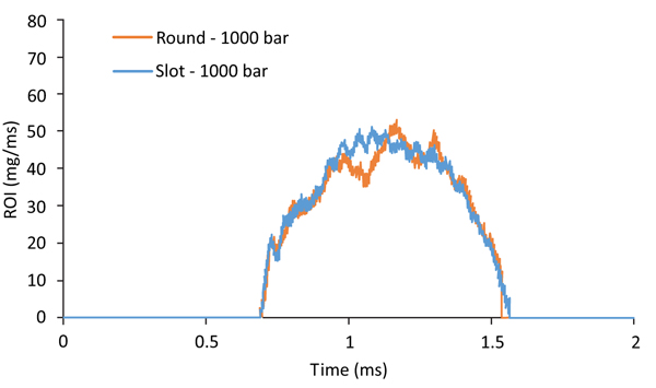 and 7
and 7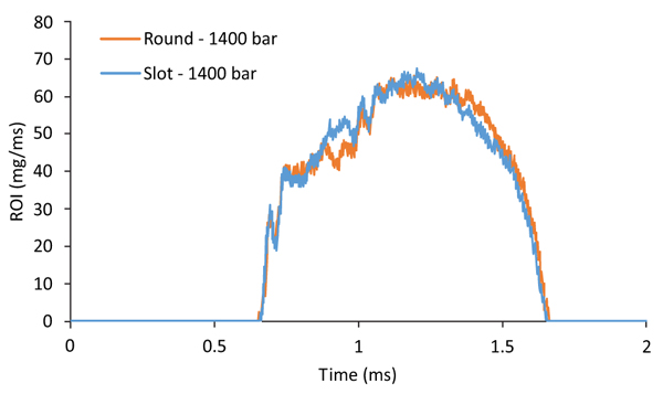 ), the ROI of the slot cases shows some deviations from the standard cases. Such deviations are located in the central injection phases. Indeed, the ROI values around to the maximum show some dependency on the type of nozzle; in the Slot case, the values reached before the maximum exceed those of the circular hole; this behavior is reversed after the maximum, in which the values relating to the Round case prevail. This behavior probably reflects that the three-dimensional flow pattern within the nozzle is affected by the hole shape. The viscous forces at the interface between fuel and the nozzle surface can also reflect the nozzle hole shape so that, among the fuel properties, viscosity could be the major factor influencing the flow development.
 |
Fig. (5) Comparison between ROI (Rate of injection) curves – 700 bar injection pressure. |
 |
Fig. (6) Comparison between ROI (Rate Of Injection) curves – 1000 bar injection pressure. |
 |
Fig. (7) Comparison between ROI (Rate of Injection) curves – 1400 bar injection pressure. |
3.2. Spray Penetration Distance
The layout of the nozzle hole cross section influences the spray development, depending on the injection pressure. At relatively low pressure (700 bar), the penetration trends are quite similar, (Fig. 8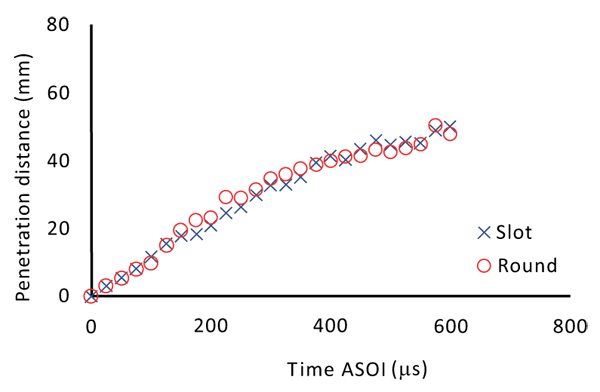 ).
).
 |
Fig. (8) Spray penetration distance vs. time; 700 bar rail pressure. |
As the injection pressure increases (1000 bar injection pressure, Fig. (9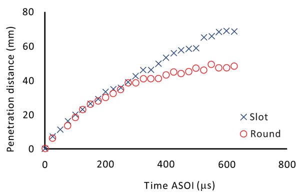 ) the spray produced by the Slot hole is characterized by a more marked penetration.
 |
Fig. (9) Spray penetration distance vs. time; 1000 bar rail pressure. |
The higher is the injection pressure, the higher is the difference between the trends, Fig. (10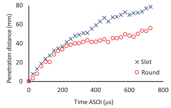 ). Compared to the 1000 bar case, the instant at which the trends detach from each other is moved backward in time and the difference in the penetration exceeds 20 mm.
 |
Fig. (10) Spray penetration distance vs. time; 1400 bar rail pressure. |
3.3. Spray Angle
The results reported in the following show that the nozzles hole layout causes a significant influence also on the spray angle. The differences were sought both close to the hole outlet section and in the so-called “steady” spray portion, in agreement with what is reported in the literature [23Desantes, J.M.; Payri, R.; Salvador, F.J.; Gil, A. Development and validation of a theoretical model for diesel spray penetration. Fuel, 2006, 85(7-8), 910-917.
[http://dx.doi.org/10.1016/j.fuel.2005.10.023] , 24Shao, J.; Yan, Y. Digital imaging based measurement of diesel spray characteristics. IEEE Trans. Instrum. Meas., 2008, 57(9), 2067-2073.].
3.4. Near Spray Region
The near spray region is identified by the distance from the hole exit section, when it equals 60 times the diameter of the round hole, that is to say 16.2 mm. According to such a definition, the near spray angles are compared; in case of Slot layout a greater opening of the spray is found.
This effect is somewhat appreciable at 700 bar, (Fig. 11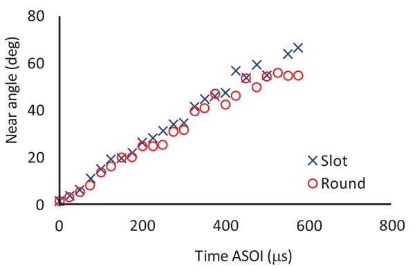 ), but it becomes significant with increasing injection pressure. In fact, while in the Round case the jet opening grows slightly due to the rise of pressure, the Slot layout widens about 20 degree the spray angle at a maximum injection pressure, (Fig. 12
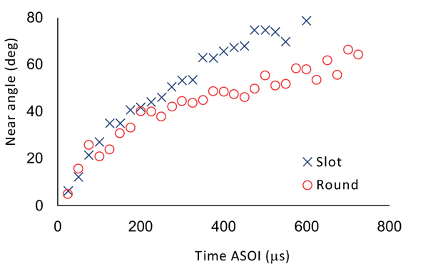 ).
).
 |
Fig. (11) Near spray angle vs. time; 700 bar rail pressure, XY plane. |
 |
Fig. (12) Near spray angle vs. time; 1400 bar rail pressure, XY plane. |
3.5. Steady Spray Region
Also considering the overall spray region, differences in the opening angle are observable. The injection pressure level still exerts an interesting role on the spray development. At low pressure, in the first 100 μs of injection, the Slot hole produces wider sprays, reaching double values in respect to the standard case, (Fig. 13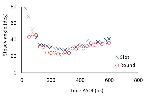 ). Such effect is reduced at higher pressure levels; the high values were seen in the first instants of injection disappear and the angle values are similar to the Round case; significant differences, around ten degrees, are instead observed in the second half of the injection process, (Fig. 14
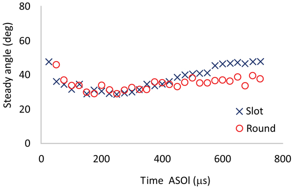 ).
).
 |
Fig. (13) Steady spray angle vs. time; 700 bar rail pressure, XY plane. |
 |
Fig. (14) Steady spray angle vs. time; 1400 bar rail pressure, XY plane. |
The visualization of spray angle needs to be completed on the “minor” plane (ZY plane). With reference to Fig. (2), the results obtained on the minor plane are reported in the following, pointing out the remarkable points of interest; in the case of round hole, the near angle opening on the ZY plane tends to exceed the values on the XY plane, Fig. (15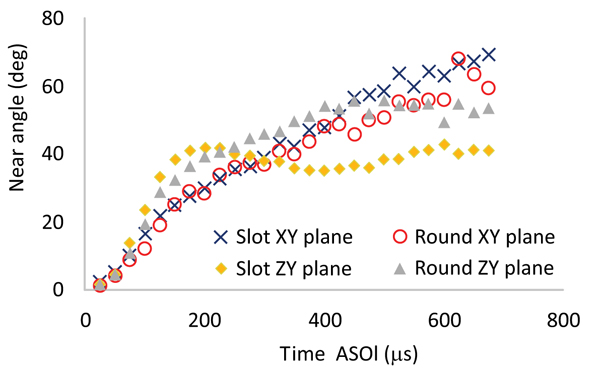 ). Since the Round hole is perfectly circular, the causes of such a difference are tied to the flow conditions at the outlet section of the hole which depends, in turn, on the whole flow pattern within the nozzle.
 |
Fig. (15) Near spray angle vs. time for the two different visualization planes; 1000 bar injection pressure. |
Regarding the Slot hole, the development of the near angle on the ZY plane shows a first phase in which the trend is dominating. In this phase the greater spray angle occurs in the minor axis direction of the Slot section, with about twenty degrees maximum difference. This condition is reversed through the progress of injection, since the max spray angle is found along the minor axis, (Fig. 15).
Also the trends of steady spray angle depend on the geometry of the hole, as shown in Fig. (16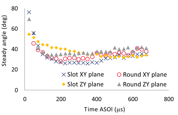 ). For both the nozzles, it was observed that the spray angle is greater on the ZY plane; in the case of the Slot geometry, this behavior is more marked.
 |
Fig. (16) Steady spray angle vs. time for the two different visualization planes; 1000 bar injection pressure. |
From a quantitative viewpoint, Fig. (17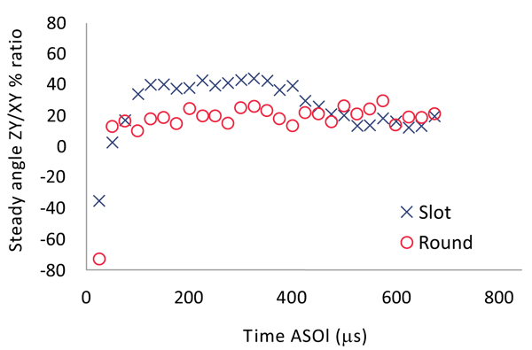 ) shows the trends of the ratio between the steady spray angles on the two viewing planes, for the Round and Slot cases. It is evident that the Slot section alters the spray symmetry, doubling the same effect observed on the standard geometry.
 |
Fig. (17) Steady spray angle XY/ZY ratio vs. time; 1000 bar injection pressure. |
CONCLUSION
A non-conventional nozzle prototype, provided with Slot holes, has been studied in comparison with a standard layout. The two nozzles under investigation have been designed and produced in the attempt to preserve the same injected mass per shot and the same rate of injection. The mechanical-hydraulic behavior of the nozzles has been assessed; then, the macroscopic spray features (penetration and spray angle) have been compared. The effect of injection pressure is explored, other conditions being the same.
The Slot hole cross section, here defined and adopted on a multihole nozzle typically used in the automotive field, has shown its influence on the spray development. In particular, the adopted “Slot nozzle” has shown the capability to increase of spray penetration for injection pressures over 1000 bar, to alter the spray angle (in the near hole exit region and in the stationary zone of the spray), to widen the spray angle in the minor axis direction (with the simultaneous reduction of the opening in the normal direction).
So far, it is possible to focus some elements helping the interpretation of the results. In the attempt to understand how these spray differences are originated, the factors that play a role in the process are considered; indeed, the increased penetration could be originated by differences in the atomization process; namely, relatively bigger droplets in the spray would penetrate faster. However, according to what reported by [13Yunyi, G.; Changwen, L.; Yezhou, H.; Zhijun, P. An experimental study on droplet size characteristics and air entrainment of elliptic sprays. SAE Tech. Pap, 1998.
[http://dx.doi.org/10.4271/982546] ], when round holes are replaced by elliptic ones (hole flow area and test conditions being the same), lower SMD of the spray is found. Thus, the increased penetration in the Slot case should be rather attributed to the alteration of the air entrainment process. The air entrainment is reflected by the spray angle, and this parameter is found to be significantly influenced by the Slot hole. In such interpretation, it is inferred that the Slot hole shape exerts a robust influence on the fuel flow pattern within the nozzle that is weakly reflected by the rate of injection but well evidenced by the spray evolution.
The adoption of the Slot holes introduces an additional feature, which can be represented by the ratio between the major and minor spray angles for a certain penetration. The obtained results also provide a contribution to the information needed to adapt the standard spray models to the cases where Slot orifice configurations are considered.
NOMENCLATURE
| Roman | = Description (Unit) |
| D | = diameter (m) |
| d | = diameter (m) |
| e | = eccentricity (m) |
LIST OF ABBREVIATIONS
| APS | = Active Pixel Sensor |
| ASOI | = After Start Of Injection |
| CMOS | = Complementary Metal-Oxide Semiconductor |
| 3D-CFD | = Three-Dimensional Computational Fluid Dynamics |
| DBI | = Diffused Back Illumination |
| ROI | = Rate Of Injection |
| SMD | = Sauter Mean Diameter |
| TB-ECU | = Test Bed Electronic Control Unit |
| DT | = Delay Time Interval |
| FPS | = Frames Per Second |
CONSENT FOR PUBLICATION
Not applicable.
CONFLICT OF INTEREST
The authors declare no conflict of interest, financial or otherwise.
ACKNOWLEDGEMENTS
This research did not receive any specific grant from funding agencies in the public, commercial, or not-for-profit sectors.
REFERENCES
| [1] | Chiatti, G.; Chiavola, O.; Palmieri, F. Diesel nozzle flow investigation in non-radial multi hole geometry. ASME 2014 Internal Combustion Engine Division Fall Technical Conference, ICEF 2014 [http://dx.doi.org/10.1115/ICEF2014-5556] |
| [2] | Chiatti, G.; Chiavola, O.; Palmieri, F. Flow features in reduced dwell time diesel injector. SAE Tech. Pap., 2008. |
| [3] | Chiatti, G.; Chiavola, O.; Frezzolini, P.; Palmieri, F. On the link between diesel spray asymmetry and off-axis needle displacement. Appl. Sci. (Basel), 2017, 7(4), 375. [http://dx.doi.org/10.3390/app7040375] |
| [4] | Payri, R.; Viera, J.P.; Gopalakrishnan, V.; Szymkowicz, P.G. The effect of nozzle geometry over ignition delay and flame lift-off of reacting direct-injection sprays for three different fuels. Fuel, 2017, 199, 76-90. [http://dx.doi.org/10.1016/j.fuel.2017.02.075] |
| [5] | Mohammadi, H.; Jabbarzadeh, P.; Jabbarzadeh, M.; Shrevani-Tabar, M.T. Numerical investigation on the hydrodynamics of the internal flow and spray behavior of diesel fuel in a conical nozzle orifice with the spiral rifling like guides. Fuel, 2017, 196, 419-430. [http://dx.doi.org/10.1016/j.fuel.2017.01.094] |
| [6] | Ganippa, L.C.; Andersson, S.; Chomiak, J.; Matsson, A. Combustion characteristics of diesel sprays from equivalent nozzles with sharp and rounded inlet geometries. Combust. Sci. Technol., 2003, 175(6), 1015-1032. [http://dx.doi.org/10.1080/00102200302350] |
| [7] | Payri, R.; García, J.M.; Salvador, F.J.; Gimeno, J. Using spray momentum flux measurements to understand the influence of diesel nozzle geometry on spray characteristics. Fuel, 2005, 84(5), 551-561. [http://dx.doi.org/10.1016/j.fuel.2004.10.009] |
| [8] | Payri, R.; Salvador, F.J.; Gimeno, J.; Zapata, L.D. Diesel nozzle geometry influence on spray liquid-phase fuel penetration in evaporative conditions. Fuel, 2008, 87(7), 1165-1176. [http://dx.doi.org/10.1016/j.fuel.2007.05.058] |
| [9] | Som, S.; Ramirez, A.I.; Longman, D.E.; Aggarwal, S.K. Effect of nozzle orifice geometry on spray, combustion, and emission characteristics under diesel engine conditions. Fuel, 2011, 90(3), 1267-1276. [http://dx.doi.org/10.1016/j.fuel.2010.10.048] |
| [10] | Amini, G.; Dolatabadi, A. Breakup of liquid jets emerging from elliptic orifices. 2011 Proceedings of the ASME Turbo Expo, 2 (PARTS A AND B), 417-414. [http://dx.doi.org/10.1115/GT2011-45390] |
| [11] | Kasyap, T.V.; Sivakumar, D.; Raghunandan, B.N. Breakup of liquid jets emanating from elliptical orifices at low flow conditions. Spray., 2008, 18(7), 645-668. [http://dx.doi.org/10.1615/AtomizSpr.v18.i7.30] |
| [12] | Kasyap, T.V.; Sivakumar, D.; Raghunandan, B.N. Flow and breakup characteristics of elliptical liquid jets. Int. J. Multiph. Flow, 2009, 35(1), 8-19. [http://dx.doi.org/10.1016/j.ijmultiphaseflow.2008.09.002] |
| [13] | Yunyi, G.; Changwen, L.; Yezhou, H.; Zhijun, P. An experimental study on droplet size characteristics and air entrainment of elliptic sprays. SAE Tech. Pap, 1998. [http://dx.doi.org/10.4271/982546] |
| [14] | Jacobsson, L.; Chomiak, J. Injection orifice shape: Effects on combustion and emission formation in diesel engines. SAE Tech. Pap, 1997. [http://dx.doi.org/10.4271/972964] |
| [15] | Jacobsson, L.; Winklhofer, E.; Chomiak, J. Injection orifice shape: Effects on spray characteristics and heat-release rate in a large-size single-cylinder diesel engine. SAE Tech Pap., 1999. |
| [16] | Matsson, A.; Jacobsson, L.; Andersson, S. The effect of elliptical nozzle holes on combustion and emission formation in a heavy duty diesel engine. SAE Tech. Pap., 2000. |
| [17] | Molina, S.; Salvador, F.J.; Carreres, M.; Jaramillo, D. A computational investigation on the influence of the use of elliptical orifices on the inner nozzle flow and cavitation development in diesel injector nozzles. Energy Convers. Manage., 2014, 79, 114-127. [http://dx.doi.org/10.1016/j.enconman.2013.12.015] |
| [18] | Hong, J.G.; Kun, W.S.; Kim, R.; Lee, C.W. Effect of cavitation in circular nozzle and elliptical nozzles on the spray characteristic. Spray., 2010, 20(10), 887-886. [http://dx.doi.org/10.1615/AtomizSpr.v20.i10.40] |
| [19] | Chiatti, G.; Palmieri, F. Hole cross section shape influence on diesel nozzle flow. SAE Tech. Pap., 2013. |
| [20] | Bosch, W. The fuel rate indicator: A new measuring instrument for display of the characteristics of individual injection. SAE Tech. Pap, 1966. [http://dx.doi.org/10.4271/660749] |
| [21] | Kostas, J.; Honnery, D.; Soria, J. Time resolved measurements of the initial stages of fuel spray penetration. Fuel, 2009, 88(11), 2225-2237. [http://dx.doi.org/10.1016/j.fuel.2009.05.013] |
| [22] | Eagle, E.W.; Morris, S.B.; Wooldridge, M.S. High-speed imaging of transient diesel spray behavior during high pressure injection of a multi-hole fuel injector. Fuel, 2014, 116, 299-309. [http://dx.doi.org/10.1016/j.fuel.2013.07.120] |
| [23] | Desantes, J.M.; Payri, R.; Salvador, F.J.; Gil, A. Development and validation of a theoretical model for diesel spray penetration. Fuel, 2006, 85(7-8), 910-917. [http://dx.doi.org/10.1016/j.fuel.2005.10.023] |
| [24] | Shao, J.; Yan, Y. Digital imaging based measurement of diesel spray characteristics. IEEE Trans. Instrum. Meas., 2008, 57(9), 2067-2073. |