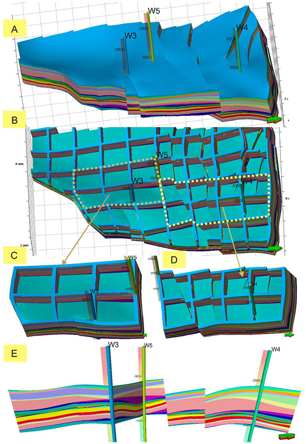
Fig. (5)
3D geological model of the study area, showing the structural model including the fence model and cross-well profile. A: 3D regional geological model of the study area; B: Three dimensional structural fence model of (A) at X-axis (1, 1, 10), Y-axis (1, 1, 10) and Z-axis (13, 27, 27); C, D: Zoomed-in views of the left black boxes in (B) at X-axis (23, 78, 1) and Y-axis (45, 45, 1), X-axis(34, 45, 1) and Y-axis (56, 1, 1), respectively, showing a detailed distribution pattern of structural model; E: Through well structural sections, showing the spatial stratigraphic distribution between wells in each layer.