- Home
- About Journals
-
Information for Authors/ReviewersEditorial Policies
Publication Fee
Publication Cycle - Process Flowchart
Online Manuscript Submission and Tracking System
Publishing Ethics and Rectitude
Authorship
Author Benefits
Reviewer Guidelines
Guest Editor Guidelines
Peer Review Workflow
Quick Track Option
Copyediting Services
Bentham Open Membership
Bentham Open Advisory Board
Archiving Policies
Fabricating and Stating False Information
Post Publication Discussions and Corrections
Editorial Management
Advertise With Us
Funding Agencies
Rate List
Kudos
General FAQs
Special Fee Waivers and Discounts
- Contact
- Help
- About Us
- Search


The Open Mechanical Engineering Journal
(Discontinued)
ISSN: 1874-155X ― Volume 14, 2020
Optimization of the Location of the Oil Cooling Gallery in the Diesel Engine Piston
Lijun Deng1, Yongqi Liu2, *, Zhiming Wang1, Shiying Liu2, Jian Zhang3
Abstract
The oil cooling gallery is arranged at the top of the piston, which can effectively reduce the heat load of the piston. In this paper, finite element analysis and fatigue analysis by FE-safe are used to calculate the effects of the different positions of the oil cooling gallery to the temperature, stress field and the fatigue strength of the bowl rim, top land, first ring groove, second land and cooling gallery. The results show that, with the oil cooling gallery moving upward regularly, the temperature of the oil cooling gallery increased, and the temperature of other piston critical position decreased; but when the distance of the oil cooling gallery and combustion chamber decreased, the structural strength of the combustion chamber decreases gradually. In addition, too small distance between the oil cooling gallery and the top surface will make the temperature of the oil cooling gallery too high, which makes the oil coking in the oil cooling gallery, affecting the cooling effect seriously. For this type of piston, the optimal distance between the oil cooling gallery and the top surface is 12.5mm.
Article Information

Identifiers and Pagination:
Year: 2016Volume: 10
First Page: 126
Last Page: 134
Publisher Id: TOMEJ-10-126
DOI: 10.2174/1874155X01610010126
Article History:
Received Date: 26/10/2015Revision Received Date: 29/1/2016
Acceptance Date: 1/2/2016
Electronic publication date: 13/06/2016
Collection year: 2016
open-access license: This is an open access article licensed under the terms of the Creative Commons Attribution-Non-Commercial 4.0 International Public License (CC BY-NC 4.0) (https://creativecommons.org/licenses/by-nc/4.0/legalcode), which permits unrestricted, non-commercial use, distribution and reproduction in any medium, provided the work is properly cited.
* Address correspondence to this author at the School of Traffic & Vehicle Engineering, Shandong University of Technology, Zibo 255049, China; E-mail: liuyq65@163.com
| Open Peer Review Details | |||
|---|---|---|---|
| Manuscript submitted on 26-10-2015 |
Original Manuscript | Optimization of the Location of the Oil Cooling Gallery in the Diesel Engine Piston | |
1. INTRODUCTION
The working environment for the engine piston is critical, it has to bear the effect of the thermal load during operation [1H. Zhang, Z. Lin, and J. Xing, "Temperature field analysis to gasoline engine piston and structure optimization", J. Theor. Appl. Inf. Technol., vol. 48, pp. 904-910, 2013.]. The highest working temperature and the temperature gradient of the critical position in the piston temperature distributions are concerned mostly, the maximum temperature affects the variation of the piston material properties and swelling quantity, and the temperature gradient is the main reason causing the heat distortion and the thermal stress. So in the design process, it is very certainly necessary to calculate and analyze the piston temperature field, and to take effective measures to reduce the thermal stress in order to increase the ability to withstand the thermal load of the piston. Piston cooling technology is an effective method to solve these problems [2J. Manuel, A. Aguilar, and R.L. Arroyo, "Study of the thermal structural behavior of a piston with gallery through finite element method", Int. Mech. Eng. Congress Expo. (ASME), pp. 759-767, 2012.
[http://dx.doi.org/10.1115/IMECE2012-93372] , 3Y. Zhang, L. Zhang, Z. Shen, Q. Si, and Z. Xu, "Finite element of piston thermal structural strength analysis of oscillating oil cooling gallery", Chin. Intern. Comb. Engine Eng., vol. 25, pp. 56-59, 2004.]. The purpose of using the cooling gallery is to reduce the temperature of the piston top surface [4N. Haiqiang, S. Ping, and M. Deqing, "The temperature experiment and thermo-mechanical coupled simulation of high-speed diesel engine piston", Chin. Intern. Comb. Engine Eng., vol. 35, pp. 105-109, 2014.] and piston ring groove portion (particularly the first and second groove), so that temperature of all critical position in the piston will be controlled in a reasonable limits [5A.K. Agarwal, and M.B. Varghese, "Numerical investigations of piston cooling using oil jet in heavy duty diesel engines", Int. J. Engine Res., vol. 7, pp. 411-421, 2006.
[http://dx.doi.org/10.1243/14680874JER01804] ].
In this paper, optimization was performed for piston with oil cooling gallery to get better cooling performance and piston reliability. Using numerical simulation for analysis, changing the positions of the oil cooling gallery to compare the temperature, stress and fatigue strength of the critical position, such as the combustion chamber, oil cooling gallery. The influence of the location of the oil cooling gallery to the critical position of the piston is obtained, which provides a theoretical basis for the design of the oil cooling gallery.
2. CALCULATION METHOD OF FATIGUE
Normally, the piston has a fatigue failure under the action of multiple alternating loads. The fatigue of the piston belongs to high cycle fatigue, and multi axis fatigue. In this paper, we use the theory of the stress - life curve, and carry on the multi - axis fatigue analysis according to the Goodman diagram to the theory of the equivalent average stress.
2.1. Method for Calculating the Mean Stress and Stress Amplitude
In the double logarithmic coordinate system, the stress amplitude and cyclic number are linear relationship [6Q. Hao, and Y.Q. Wang, "The study on piston pin fatigue life prediction", Mach Des. Manuf., vol. 1, pp. 129-131, 2011.]. The stress of the piston changes between the maximum stress Smax and the minimum stress Smin during a complete cycle of 720 DEG C crank angle. The difference is called strain ∆S, and the half of the difference is the stress amplitude ∆S/2.
Stress Range
 |
(1) |
The mean stress
 |
(2) |
The stress amplitude
 |
(3) |
2.2. Calculation Method of the Fatigue Coefficient
The relationship between the cyclic stress amplitude and the equivalent average stress is studied in the given life. When the life is certain, the greater of the equivalent average stress, the smaller of the corresponding stress amplitude. However, the equivalent average stress will never be greater than the destructive strength in either case. The failure strength is the yield limit of the material which has good ductility or tensile strength of the modified materials [7Y. Guo, "The Study on the Prediction Method of Mechanical Fatigue Life for the Heavy Duty Diesel Engine Piston", M.S. thesis, North University of China, Taiyuan, China, 2012.].
For any given life, the most severe cycle, i.e. the one that comes closest to the Goodman line, is plotted on the Goodman diagram. A line is drawn through this point from the origin. This indicates how much the stress could be increased before it touches the Goodman line. As shown in Fig. (1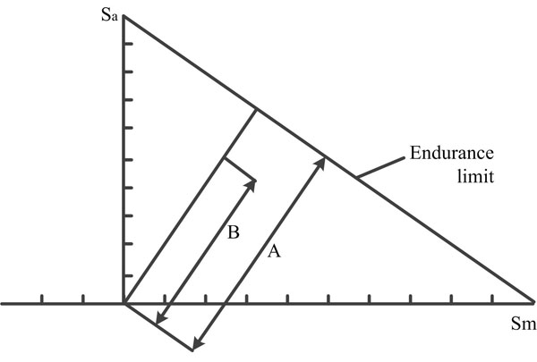 ), the ratio A/B indicates the fatigue factor.
 |
Fig. (1) Factor of strength (FOS)-Goodman diagram. |
3. RESEARCH AND ANALYZES
In order to find the reasonable position of the oil cooling gallery, one type of diesel engine piston was analyzed in this paper. The specific parameters of the engine are shown in Table 1. The main purpose is focus on the effect of different locations of the cooling gallery to the temperature and fatigue fields of piston critical position. In order to ensure the accuracy of the piston temperature field, using the measured temperature data from templug test to verify.

As the internal combustion engine works, the piston is also influenced by the gas pressure from the cylinder. Therefore, the connecting rod and piston pin should be considered into the modeling. The piston used for the present investigation in the finite element analysis adopts aluminum alloy material, the material properties are described in Table 2.

The piston element type is usually defined as Solid187, and the piston pin is defined as Solid186. The mentioned proper piston material features and entity unit type were used for intellectual finite element mesh division. In order to better present the law of data change and save computation time, to use relatively dense grid for the temperature gradient of the larger part (such as the combustion chamber), and to use relatively sparse grid in the lower temperature gradient. The mesh information of the piston is shown in Table 3.

 |
Fig. (2) The finite element mesh. |
By establishing a model of a certain type of internal combustion engine piston, pin and connecting rod, the finite element mesh of the piston is shown in Fig. (2 ). The temperature distribution of the piston is assumed to remain constant all the time. In the simulation, we usually set a unified environment temperature at the top of the piston, but the heat transfer coefficient needs to be divided into four zones. In general, the center of the combustion chamber is the first zone, the bottom of the combustion chamber is the second zone, the combustion bowl rim is the third zone, and the annular region on top surface is the fourth zone. Lands and ring grooves are divided into six zones. The top land, upper and back faces of the first ring groove are the fifth zone, lower face of the first ring groove is the sixth zone, The second land, upper and back faces of the second ring groove are the seventh zone, lower face of the second ring groove is the eighth zone, The third land, upper and back faces of the third ring groove are the ninth zone, lower face of the third ring groove is the tenth zone. The value of heat transfer coefficient and ambient temperature in different zones are shown in the Table 4.

During the calculation, on one hand the gas pressure load and the inertia force are considered, on the other hand, when the piton moves up and down, the side force also need to be considered. The contacts between pin and bore, piston skirt and liner, connecting rod and pin are considered. In solver module, special parameters was used to calculate the temperature field and stress field. In the meantime, the residual series curve was used to track the calculation process, finally we get temperature field, and stress field, etc. The temperature calculation of results field are shown in Fig. (3 ). From the calculation of the temperature field results, the temperature of the critical position of the piston, as combustion bowl rim, the top surface of piston and the first ring groove are higher, the highest temperature of the combustion bowl rim reached 323 degrees.
 |
Fig. (3) Results of the temperature fields. |
 |
Fig. (4) Electronic micro hardness tester. |
In this paper, the temperature field of finite element simulation analysis is demarcated and verified by using the method of templug. The method of templug [8J. Zhong, "Piston Injection Oscillation Cooling Stability, Transient Simulation and the Piston Temperature Field Analysis", M.S. thesis, Shandong University, Ji'nan, China, 2012., 9N. Haiqiang, C. Yufeng, and H. Xinghua, "Thermal load simulation and structure optimization of high speed diesel engine piston", Mach. Des. Manuf., vol. 5, pp. 195-197, 2014.] is usually a way to get the temperature of the piston, and the principle of templug method is as follows. When metal material tempering after quenching, the amount of hardness loss depends on the maximum temperature and the duration of this temperature. If the duration is defined, the relationship curve between temperature and hardness can be established, and then measure the change of material hardness. Finally get the reasonable external temperature according to the curve.
 |
Fig. (5) The location of the piston surface temperature measuring point. |
 |
Fig. (6) Temperature distribution of critical position. |
During the engine trial, first select the different tempering temperature, tempering on the hardness plug for a certain period of time, and measure the corresponding hardness value, to make the hardness and temperature corresponding to the HV-T curve. The calibration of the HV-T curve of the hardness plug is the basis of the temperature field test. And the accuracy of the temperature test is directly determined by the accuracy of the curve calibration. When the curve is calibrated, tempering temperature is generally in the range of 100-400 DEG C, test at every 15 DEG C, each six hardness plugs are placed in dry oven for isothermal tempering 2 hours, after that natural cooling at room temperature, then using the electronic micro hardness tester (as shown in Fig. 4 ) to test the hardness value of the Vivtorinox after tempering. Finally, HV-T calibration curve is made according to the corresponding hardness value of different tempering temperature.
Several measurement points were set on the surface of the piston calibration curve for the thermal plugs and the temperature of piston were obtained. The measuring points are shown in Fig. (5 ). Then, the hardness plug is installed in the piston part which needs to be tested after installing hardness plug into the piston, the piston is installed into the engine.
Run the engine for 30mins to warm up, then run for another two hours at rated condition, and remove the hardness plug when the engine stops. Mark the hardness plug according to the arrangement of points, and measure the hardness value of the hardness plug by electronic micro hardness tester. Finally, the temperature values are obtained in the HV-T standard curve, which are the measured points in the test condition, and the results are shown in Fig. (6 ).
).
According to the results of temperature fields (Fig. 3), and the measured values (Fig. 6), critical position temperature comparison was made between the simulation results of and the measured value, as shown in Table 5.

By contrast, the simulation results and experimental results show that the location of highest temperature value in simulation calculation is consistent with the location of experiment, the maximum temperature points are both on combustion bowl rim. The maximum value of piston temperature field simulation calculation is 323 degrees, the temperature value of the experimental results of combustion bowl rim is 327 degrees, and a difference of 4 degrees, the relative tolerance is 1.2%, and it’s within the allowed tolerance range, so the result from the finite element can be accepted.
3.2. Effect of Oil Cooling Gallery Position on Temperature Field of Piston
The temperature at the first ring groove has great influence on the coking of oil, when the ring groove area temperature cannot bear the temperature, tend to cause chemical fission of lubricating oil and formatting carbon deposition at the root of the ring groove, resulting in deterioration of oil coking. When the carbon deposition to a certain extent will hinder the movement of the piston ring, or even the ring groove completely blocked, resulting in the ring locked in the first ring groove. At the same time, the carbon deposition as the thermal insulation of the ring groove system, can hinder the thermal conduction from the piston to the cylinder wall, then the partial piston temperature is increased [10W. Zhang, Y. Cao, Y.P. Yuan, and Z. Yang, "Simulation study of flow and heat transfer in oscillating cooling pistons based on CFD", T CSICE., vol. 28, pp. 74-78, 2010., 11Y. Feng, and Y. Zhang, "The effect of the position of oscillating oil cooling gallery to the temperature field of the diesel engine piston", Eqpt. Manuf. Technol., vol. 62, pp. 11-13, 2009.].
In this paper, by changing the position of the oil cooling gallery in the piston, analyze the effect of oil cooling gallery position variations to the temperature distribution of the piston critical position, and the schematic diagram of oil cooling gallery is shown in Fig. (7 ). By the internal combustion engine piston FEA results in Table 6, we can see that the changes of oil cooling gallery position influence the heat transfer characteristics of the oil cooling gallery, and then change the temperature field of piston. So as the oil cooling gallery position changes, the temperature of the critical position also shows some changes.
 |
Fig. (7) Schematic diagram of different schemes of oil cooling gallery. |

Based on the established geometrical model and with the finite element analysis, we can calculate and get results as shown in Table 6. Comparing the results of the different positions, we can clearly see that the closer of the distance between the oil cooling gallery and the piston top surface, or between the oil cooling gallery and combustion chamber, the higher of the temperature of oil cooling gallery, oil cooling gallery can take away more heat, so that the temperature of the critical position of the piston decrease, such as combustion bowl rim, the top and the second land and the first ring groove; conversely, with the distance of the oil cooling gallery and the piston top surface increase, the temperature of the critical position of the piston increase regularly, these critical positions are combustion bowl rim, the first and the second land and the first ring groove.
Up-position cooling gallery is used more widely for decreasing the piston crown temperature, but the distance between crown surface and upper cooling gallery zone should be limited.
Because with the decreasing of the distance of the oil cooling gallery and the piston top surface, the distance of the oil cooling gallery and combustion chamber is also getting close, which leads to structural strength reduction, and then impact the reliability of the whole head of piston. In addition, too small distances will cause much higher temperature of the oil cooling gallery, and resulting the oil coking in the oil cooling gallery, affecting the cooling effect seriously.
3.3. Effect of Oil Cooling Gallery Position on Stress Field of Piston
The high temperature and temperature gradient of the piston will inevitably cause thermal deformation and thermal stress. The finite element analysis of the stress field, using temperature field of the piston as the heat load of the piston, and then coupling with the inertia force and the lateral force indirectly, to obtain the thermal deformation and thermal stress.

The stress results of the finite element simulation of the piston are shown in Fig. (8 ). And where in the X axis stands for the distance of the oil cooling gallery and the piston top surface, and also stand for the distance of the oil cooling gallery and the combustion chamber; Y axis stands for the hoop stress value of combustion chamber. The finite element calculation results show that with decreasing the distance of the oil cooling gallery and the piston top surface, or along to the distance of the oil cooling gallery and the combustion chamber, the combustion chamber hoop stress increases. However, the various is not obvious in the beginning, when H is in the range of 14.5mm to 10.5mm, the distance of the oil cooling gallery and the combustion chamber get closer and closer, at this range, the principal stress rise sharply. The results show that the location of oil cooling gallery effect the stress of combustion chamber seriously when the distance is too close.

3.4. Research and Analysis of Piston Strength
When the piston works, the critical position such as the combustion chamber, skirt, and pinhole often cracks, most of the cracking are caused by fatigue of their materials.
The fatigue analysis results of oil cooling gallery and combustion chamber are shown in Fig. (9 ). Where in the X axis stands for the distance of the oil cooling gallery and the piston top surface and also stands for the distance of the oil cooling gallery and the combustion chamber Y axis stands for fatigue factor value of the critical position. The results show that the fatigue factor of the minimum distance of the oil cooling gallery within the combustion chamber and the maximum stress of the combustion chamber in the same position. Furthermore, from Fig. (9) it can be seen that, when H=12.5m, the fatigue factor of the cooling gallery is higher than the experience standard value 1.0; at the beginning (H=18.5mm), the fatigue factor of the combustion chamber changes not obviously along with the oil cooling gallery moves up. However, when H is from 12.5mm to 10.5mm, the fatigue factor of the combustion chamber drop abruptly, and that lower than the experience standard value 1.1. The results show that the position of the oil cooling gallery only can be changed in a certain range to insure the strength of the combustion chamber.
CONCLUSION
- The oil cooling gallery can effectively reduce the temperature of the piston head. With the position of oil cooling gallery regularly moving up, the temperature of the oil cooling gallery increases, and temperature of the key positions, such as the bowl rim, top land, first ring groove, second land and cooling gallery of the internal combustion engine piston decrease.
- Results of the finite element analysis and fatigue analysis of the piston show that with the changes of the position of the oil cooling gallery in piston, the temperature, stress, and fatigue factor will change accordingly. Also, these changes influence the material character of the oil cooling gallery, influence the fatigue strength, and lead to the different cooling effects.
- The results about stress and fatigue factor of the piston critical position show that, with the position of the oil cooling gallery up to the piston top surface, the fatigue factor of the oil cooling gallery decreases, and then impacts the reliability of the whole head of piston.
- The research show that the distance between oil cooling gallery and combustion chamber of piston cannot be too small, there is a limit value, and the value should be decided by the strength of the critical position of the piston. According to the results of the simulation study, if only considering the effect of the distance of the oil cooling gallery and the piston top surface and the distance of the oil cooling gallery and combustion chamber, the research shows that the best position of oil cooling gallery is where the distance of the oil cooling gallery and the piston top surface is 12.5mm.
CONFLICT OF INTEREST
The authors confirm that this article content has no conflict of interest.
ACKNOWLEDGEMENTS
The authors sincerely thank laboratory of Bohai piston for support, cooperation and contributions. And the authors also would like to express thanks to Dr. Jia Zhenjian, Xiong Peiyou and all the partners who participated in the experiment.
REFERENCES
| [1] | H. Zhang, Z. Lin, and J. Xing, "Temperature field analysis to gasoline engine piston and structure optimization", J. Theor. Appl. Inf. Technol., vol. 48, pp. 904-910, 2013. |
| [2] | J. Manuel, A. Aguilar, and R.L. Arroyo, "Study of the thermal structural behavior of a piston with gallery through finite element method", Int. Mech. Eng. Congress Expo. (ASME), pp. 759-767, 2012. [http://dx.doi.org/10.1115/IMECE2012-93372] |
| [3] | Y. Zhang, L. Zhang, Z. Shen, Q. Si, and Z. Xu, "Finite element of piston thermal structural strength analysis of oscillating oil cooling gallery", Chin. Intern. Comb. Engine Eng., vol. 25, pp. 56-59, 2004. |
| [4] | N. Haiqiang, S. Ping, and M. Deqing, "The temperature experiment and thermo-mechanical coupled simulation of high-speed diesel engine piston", Chin. Intern. Comb. Engine Eng., vol. 35, pp. 105-109, 2014. |
| [5] | A.K. Agarwal, and M.B. Varghese, "Numerical investigations of piston cooling using oil jet in heavy duty diesel engines", Int. J. Engine Res., vol. 7, pp. 411-421, 2006. [http://dx.doi.org/10.1243/14680874JER01804] |
| [6] | Q. Hao, and Y.Q. Wang, "The study on piston pin fatigue life prediction", Mach Des. Manuf., vol. 1, pp. 129-131, 2011. |
| [7] | Y. Guo, "The Study on the Prediction Method of Mechanical Fatigue Life for the Heavy Duty Diesel Engine Piston", M.S. thesis, North University of China, Taiyuan, China, 2012. |
| [8] | J. Zhong, "Piston Injection Oscillation Cooling Stability, Transient Simulation and the Piston Temperature Field Analysis", M.S. thesis, Shandong University, Ji'nan, China, 2012. |
| [9] | N. Haiqiang, C. Yufeng, and H. Xinghua, "Thermal load simulation and structure optimization of high speed diesel engine piston", Mach. Des. Manuf., vol. 5, pp. 195-197, 2014. |
| [10] | W. Zhang, Y. Cao, Y.P. Yuan, and Z. Yang, "Simulation study of flow and heat transfer in oscillating cooling pistons based on CFD", T CSICE., vol. 28, pp. 74-78, 2010. |
| [11] | Y. Feng, and Y. Zhang, "The effect of the position of oscillating oil cooling gallery to the temperature field of the diesel engine piston", Eqpt. Manuf. Technol., vol. 62, pp. 11-13, 2009. |