- Home
- About Journals
-
Information for Authors/ReviewersEditorial Policies
Publication Fee
Publication Cycle - Process Flowchart
Online Manuscript Submission and Tracking System
Publishing Ethics and Rectitude
Authorship
Author Benefits
Reviewer Guidelines
Guest Editor Guidelines
Peer Review Workflow
Quick Track Option
Copyediting Services
Bentham Open Membership
Bentham Open Advisory Board
Archiving Policies
Fabricating and Stating False Information
Post Publication Discussions and Corrections
Editorial Management
Advertise With Us
Funding Agencies
Rate List
Kudos
General FAQs
Special Fee Waivers and Discounts
- Contact
- Help
- About Us
- Search


The Open Mechanical Engineering Journal
(Discontinued)
ISSN: 1874-155X ― Volume 14, 2020
Ludwick Cantilever Beam in Large Deflection Under Vertical Constant Load
Alberto Borboni*, 1, Diego De Santis1, Luigi Solazzi1, Jorge Hugo Villafañe2, Rodolfo Faglia1
Abstract
The aim of this paper is to calculate the horizontal and vertical displacements of a cantilever beam in large deflections. The proposed structure is composed with Ludwick material exhibiting a different behavior to tensile and compressive actions. The geometry of the cross-section is constant and rectangular, while the external action is a vertical constant load applied at the free end. The problem is nonlinear due to the constitutive model and to the large deflections. The associated computational problem is related to the solution of a set of equation in conjunction with an ODE. An approximated approach is proposed here based on the application Newton-Raphson approach on a custom mesh and in cascade with an Eulerian method for the differential equation.
Article Information

Identifiers and Pagination:
Year: 2016Volume: 10
First Page: 23
Last Page: 37
Publisher Id: TOMEJ-10-23
DOI: 10.2174/1874155X01610010023
Article History:
Received Date: 24/03/2015Revision Received Date: 16/9/2015
Acceptance Date: 17/9/2015
Electronic publication date: 28/03/2016
Collection year: 2016
open-access license: This is an open access article licensed under the terms of the Creative Commons Attribution-Non-Commercial 4.0 International Public License (CC BY-NC 4.0) (https://creativecommons.org/licenses/by-nc/4.0/legalcode), which permits unrestricted, non-commercial use, distribution and reproduction in any medium, provided the work is properly cited.
* Address correspondence to this author at the Università degli Studi di Brescia - Mechanical and Industrial Engineering Department, Via Branze, 38 – 25123 Brescia, Italy; Tel: +390303715401; E-mail: alberto.borboni@ing.unibs.it
| Open Peer Review Details | |||
|---|---|---|---|
| Manuscript submitted on 24-03-2015 |
Original Manuscript | Ludwick Cantilever Beam in Large Deflection Under Vertical Constant Load | |
1. INTRODUCTION
Different authors studied the effect of flexibility on mechanisms and machine applications [1F. Guan, C. Zhou, and Q. Huang, "An innovative planetary gear reducer with overcoming the “dead point”", Open Mech. Eng. J., vol. 7, pp. 70-75, 2013.
[http://dx.doi.org/10.2174/1874155X01307010070] -5D. Yang, H. Cui, X. Tian, Q. Zhang, and P. Xu, "Research on tooth modification of spur bevel gear", Open Mech. Eng. J., vol. 5, pp. 68-77, 2011.
[http://dx.doi.org/10.2174/1874155X01105010068] ]. Effects of stiffness and deflections are important in different mechanical fields, i.e. industrial, biomedical [6E. Armentani, F. Caputo, and R. Citarella, "Fem sensitivity analyses on the stress levels in a human mandible with a varying atm modelling complexity", Open Mech. Eng. J., vol. 4, pp. 8-15, 2010.-9B. Zheng, Y. Liu, and R. Liu, "Stress and fatigue of connecting rod in light vehicle engine", Open Mech. Eng. J., vol. 7, pp. 14-17, 2013.
[http://dx.doi.org/10.2174/1874155X01307010014] ]. In the followings, we describe a route of scientific studies that drives to the state of the art on Ludwick materials. Literature [10K. Bisshopp, and D. Drucker, "Large deflection of cantilever beams", Q. Appl. Math., vol. 3, pp. 272-275, 1945.] proposed a description of a cantilever beam subjected to large deformation with a vertical action at the free end and composed by Ludwick non-linear elastic material. Then, literature [11C.C. Lo, and S. Das Gupta, "Bending of a nonlinear rectangular beam in large deflection", J. Appl. Mech., vol. 45, pp. 213-215, 1978.
[http://dx.doi.org/10.1115/1.3424238] ] solved the problem associated to the large deflections of non-linear elastic beams with a constitutive model described by a logarithmic law. Successively [12G. Lewis, and F. Monasa, "Large deflections of cantilever beams of nonlinear materials", Comput. Struct., vol. 14, pp. 357-360, 1981.
[http://dx.doi.org/10.1016/0045-7949(81)90054-7] ] the problem of a cantilever beam with a symmetric Ludwick constitutive law and subjected to a vertical constant force at the free bound was solved numerically. An analytic solution of a similar problem was found by the same authors for cantilever beams subject to a constant rotary load at the free bound [13G. Lewis, and F. Monasa, "Large deflections of cantilever beams of non-linear materials of the Ludwick type subjected to an end moment", Int. J. Non-linear Mech., vol. 17, pp. 1-6, 1982.
[http://dx.doi.org/10.1016/0020-7462(82)90032-4] ]. Then the issue of large deformation of a Ludwick structures [14K. Lee, "Large deflections of cantilever beams of non-linear elastic material under a combined loading", Int. J. Non-linear Mech., vol. 37, pp. 439-443, 2002.
[http://dx.doi.org/10.1016/S0020-7462(01)00019-1] ] was treated numerically on a cantilever beam subjected to two mechanical loads: a distributed vertical load on the beam in addition to a constant vertical force at the free bound. Other authors [15C. Baykara, U. Guven, and I. Bayer, "Large deflections of a cantilever beam of nonlinear bimodulus material subjected to an end moment", J. Reinf. Plast. Compos., vol. 24, pp. 1321-1326, 2005.
[http://dx.doi.org/10.1177/0731684405049857] ] described thin cantilever beams composed by bimodulus Ludwick type material under the presence of a mechanical moment applied at the free-end. A semi-exact solution was achieved [16E. Solano-Carrillo, "Semi-exact solutions for large deflections of cantilever beams of non-linear elastic behaviour", Int. J. Non-linear Mech., vol. 44, pp. 253-256, 2009.
[http://dx.doi.org/10.1016/j.ijnonlinmec.2008.11.007] ] for cantilever beams composed by Ludwick material in large deformations and subjected to a double vertical load: the first was distributed on the beam and the second concentrated at the free end. Then non-prismatic cantilever beams composed by a generalized Ludwick material [17M. Brojan, M. Cebron, and F. Kosel, "Large deflections of non-prismatic nonlinearly elastic cantilever beams subjected to non-uniform continuous load and a concentrated load at the free end", Acta Mech. Sin., vol. 28, pp. 863-869, 2012.] were described in the presence of large deflections and external constant mechanical loads. A numerical approach was proposed [18J.T. Holden, "On the finite deflections of thin beams", Int. J. Solids Struct., vol. 8, pp. 1051-1055, 1972.
[http://dx.doi.org/10.1016/0020-7683(72)90069-8] ] for the deformation of Ludwick cantilever beams in the elastic domain using a fourth order Runge-Kutta solver. Then a similar method was proposed [19B.K. Lee, J.F. Wilson, and S.J. Oh, "Elastica of cantilevered beams with variable cross-sections", Int. J. Non-linear Mech., vol. 28, pp. 579-589, 1993.
[http://dx.doi.org/10.1016/0020-7462(93)90049-Q] ] for linear elastic cantilever beams with non-constant cross-section under different loading conditions. Likewise [20G. Baker, "On the large deflections of nonprismatic cantilevers with a finite depth", Comput. Struct., vol. 46, pp. 365-370, 1993.
[http://dx.doi.org/10.1016/0045-7949(93)90201-N] ] other authors described the mechanical behavior of linear elastic cantilever beams in large deformations under different distributed mechanical actions with an approximated approach applied to the associated Bernoulli-Euler problem.
Different authors worked on non-linear elastic materials with different constitutive models [21G. Prathap, and T.K. Varadan, "Inelastic large deformation of beams", Trans. ASME, vol. 43, pp. 689-690, 1976.
[http://dx.doi.org/10.1115/1.3423957] ], i.e. Ramberg-Osgood [22T. Varadan, and D. Joseph, "Inelastic finite deflections of cantilever beams", J. Aeron. Soc. India, vol. 39, pp. 39-41, 1987.], considering large deflections of cantilever beams under different loading conditions at the free end. Furthermore literature proposed different works on non-linear materials with variable constitutive model [23Y.A. Kang, and X.F. Li, "Bending of functionally graded cantilever beam with power-law non-linearity subjected to an end force", Int. J. Non-linear Mech., vol. 44, pp. 696-703, 2009.
[http://dx.doi.org/10.1016/j.ijnonlinmec.2009.02.016] ].
This work proposes a study on a cantilever beam with a Ludwick elastic constitutive law that is non-linear and asymmetric under large deflections. Different implementations of these results can be performed for applicative purposes, i.e. in the design of compliant mechanisms or microactuators with large deflections [24C. Amici, A. Borboni, and R. Faglia, "A compliant PKM mesomanipulator: kinematic and dynamic analyses", Adv. Mech. Eng., vol. 2010, p. 706023, 2010.-26A. Borboni, and R. Faglia, "Stochastic evaluation and analysis of free vibrations in simply supported piezoelectric bimorphs", J. Appl. Mech., vol. 80, no. 2, 2013.
[http://dx.doi.org/10.1115/1.4007721] ].
2. PROBLEM DESCRIPTION
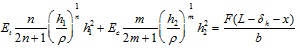
This work investigates a cantilever beam with the following characteristics: its length, at initial conditions, is L, the cross-section does not change over the time and is rectangular, the characteristic measures of the cross-section are b and h, finally the beam is subjected to a vertical constant load F at the free bound.
Fig. (1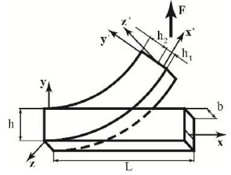 ) shows the transformation of the beam in large deflection under the effects of the constraints and of the F force applied to the free end. Fig. (1) shows the reference configuration (the initial one) and its associated reference system Oxyz. The deformed configuration can also be described with respect to this system. Another set of reference systems, O’x’y’z’, is then placed on each cross-section, with the axes positioned as shown in Fig. (1). This reference system divides each cross-section into two parts with lengths, respectively, h1 and h2 that must be computed with a proper algorithm and are, in general, characterized by the equation (1).
 |
Fig. (1) Cantilever beam in the initial and deformed configurations subjected to a constant vertical mechanical load F. |
 |
(1) |
 |
(2) |
The beam is characterized by a Ludwick non-linear constitutive law. The behavior of the beam associated to the deformation is always elastic. The material shows different characteristics when constrained to a compression or to a tension, according to [8D. Liu, H. Zhang, Z. Tao, and Y. Su, "Finite element analysis of high-speed motorized spindle based on ANSYS", Open Mech. Eng. J., vol. 5, pp. 1-10, 2011.
[http://dx.doi.org/10.2174/1874155X01105010001] ]. In detail, the proposed material has a constitutive law described by different coefficients associated to compression and tension conditions (2). Specifically the tensile and compressive Young moduli are, respectively, Et and Ec, whereas the tensile and compressive linear coefficients are, respectively, n and m.
3. PROBLEM FORMULATION
This paper deals on large deflections of a thin cantilever beam, under the hypotheses of Euler-Bernoulli. Thus a cross-section of the beam remains plane and normal to the neutral surface after a deformation and orthogonal without shape or area deformations. For these reasons, the beam can be described as a curve coincident with its neutral curve and all the cross-section properties can be associated to the crossing point of the neutral curve, as shown in Fig. (2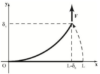 ).
).
 |
Fig. (2) Initial and deformed shape of the neutral curve of the beam. |
In the focused problem, the axial and the shear effects are small compared to those due to the bending moment. Therefore, the beam is depicted in Fig. (3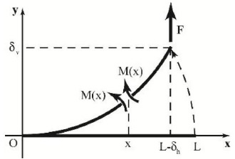 ) in the deformed configuration loaded only with a bending moment M(x) that varies with the spatial coordinate x, as described in the expression (3), that depends on the horizontal deflection of the free tip δh, on the initial length of the neutral curve of the beam L and on the vertical load applied at the free tip of the beam F.
 |
Fig. (3) Bending moment M(x) associated to a cross-section with coordinate x. |
 |
(3) |
Fig. (4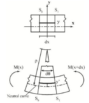 ) describes an infinitesimal part of the beam in the deformed configuration: its length is dx, while the end sections are S0 and S1. As just mentioned the deformation is due to only a bending moment M(x) that acting on the beam transforms its shape from the initial one to the final one, as further shown in Fig. (4).
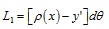
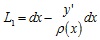
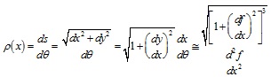
The horizontal fibre shown in Fig. (4) is distant y from the neutral curve and is exposed to an angular deformation described by the infinitesimal angle dθ. After this deformation, the length of the fibre L1 can change according to the governing equation (4); here, ρ represents the curvature radius of the neutral curve as further described in (5). Expression (6) describes the length of the fibre with respect to its initial length dx. The term y’ enhanced in (4) and (6) is the value of the final location of the horizontal fibre in the deformed configuration.
 |
(4) |
 |
Fig. (4) Infinitesimal portion of the beam under the effect of the bending moment M(x). |
 |
(5) |
 |
(6) |
The strain εx along the x’ axis (7), according to (6), can be expressed by the equation (8).
 |
(7) |
 |
(8) |
As just observed, merely the deformation due to bending moment affect the cross-sections of the beam, therefore the expressions (9-10) can describe the deformed configuration, and here σx’ is the stress along the x’ direction.
 |
(9) |
 |
(10) |
Equations (11) and (12) are just a representation of relations (9) and (10), where compressed area is distinguished from the tensile area of the cross-section.
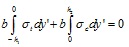 |
(11) |
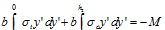 |
(12) |
Then equations (13) and (14) follow.
 |
(13) |
 |
(14) |
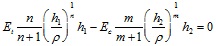
The set of equations (1), (13) and (14) refers to a non-linear algebraic problem under the unknown functions h1(x), h2(x) and ρ(x); δh is set as a tentative numerical value at the first step of the proposed solution algorithm and then is further refined to the converging solution
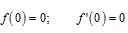
Specifically, the proposed solution algorithm assigns an initial value δ and divides the beam in different parts constructing a mesh along the x direction, the set of equation that describes the problem is solved approximatively with a Newton-Raphson method over the mesh obtaining a set of values for the unknowns of the problem: h1(x), h2(x) and ρ(x). Then, the non-linear ODE indicated in (15) is solved approximately with an Euler approach under the initial conditions described in (16).
 |
(15) |
 |
(16) |
Then, the computational procedure continues with the verification of the adopted value of ρh, namely it calculates the difference between the initial and final values of the length of the beam, verifying that it is under a set level; contrary, δh is incremented and the algorithm is restarted. Finally, the value of δv is computed with the equation indicated in (17).
 |
(17) |
Particularly, if Et and Ec are equal, also n and m, the coefficients of nonlinearity, are also equal to the value 1, the results are the same of those associated to a linear elastic material under large deflections.
4. RESULTS
To verify the algorithm, the values of δh and δv are calculated for the problem proposed by Lewis and Monasa [12G. Lewis, and F. Monasa, "Large deflections of cantilever beams of nonlinear materials", Comput. Struct., vol. 14, pp. 357-360, 1981.
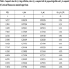
[http://dx.doi.org/10.1016/0045-7949(81)90054-7] ] and a comparison with this literature case is listed in Tables 3 and 4 for two types of material: annealed copper and NP8 aluminium alloy.
Data describing the real materials adopted in this work, annealed copper and aluminum alloy N.P.8, are shown in Table 1.
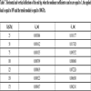
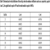
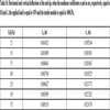
Tables 3 and 4 are devoted to compare values calculated with the proposed algorithm with those indicated by Lewis and Monasa in their work [12G. Lewis, and F. Monasa, "Large deflections of cantilever beams of nonlinear materials", Comput. Struct., vol. 14, pp. 357-360, 1981.
[http://dx.doi.org/10.1016/0045-7949(81)90054-7] ]. Specifically they are applied on a cantilever beam realized with aluminum alloy NP8. Similarly Tables 5 and 6 compare equivalent values computed on a cantilever beam realized with annealed copper. The values computed with the proposed algorithm are similar to those calculated by Lewis and Monasa in their [12G. Lewis, and F. Monasa, "Large deflections of cantilever beams of nonlinear materials", Comput. Struct., vol. 14, pp. 357-360, 1981.
[http://dx.doi.org/10.1016/0045-7949(81)90054-7] ], as also highlighted in Figs. (5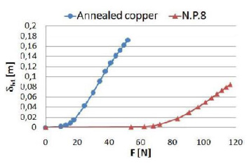 , 6
, 6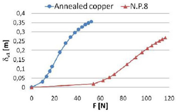 ) for a beam with a geometry described in Table 2.
 |
Fig. (5) Computed values δh1 in large deflection with the proposed algorithm on aluminium alloy N.P.8 and annealed copper beams. |
Extended numerical computations of the vertical and horizontal deflections are listed in Table 7-11 and depicted in Figs. (7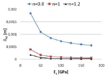 -10
-10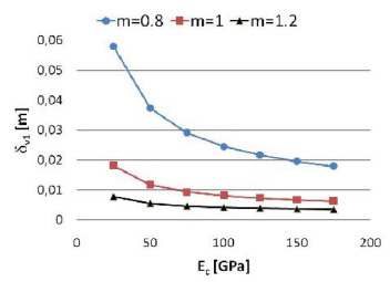 ), for a vertical external load of 10N, a tensile module of 100GPa and for variable values of Ec, n and m.
 |
Fig. (6) Computed values δv1 in large deflection with the proposed algorithm on aluminium alloy N.P.8 and annealed copper beams. |
The computed results show a relation between the deflections and the material parameters Ec, n or m under the same geometrical, constraint and load conditions.

 |
Fig. (7) Horizontal deflections of the end tip, when the nonlinear coefficient m is equal to 1, the applied load is equal to 10N and the tensile module is equal to 100GPa. |
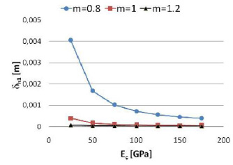 |
Fig. (8) Horizontal deflections of the end tip, when the nonlinear coefficient n is equal to 1, the applied load is equal to 10N and the tensile module is equal to 100GPa. |

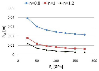 |
Fig. (9) Vertical deflections of the end tip, when the nonlinear coefficient m is equal to 1, the applied load is equal to 10N and the tensile module is equal to 100GPa. |
 |
Fig. (10) Vertical deflections of the end tip, when the nonlinear coefficient n is equal to 1, the applied load is equal to 10N and the tensile module is equal to 100GPa. |
5. FEM VALIDATION OF NUMERICAL RESULTS
In order to validate the numerical algorithm given in this paper, the vertical displacement δv and the horizontal displacement δh are calculated using the FEM software ABACUS/CAE® for a beam made of aluminium alloy N.P.8 and for a beam made of annealed copper. In ABACUS/CAE® the investigated cantilever beam is discretized using the Hex method, i.e. the beam is subdivided in parallelepipeds.
The constraint section is realized by blocking all nodes of that section. The vertical constant force F on the free section is realized by four equal forces applied on the nodes of the four corners of the free section. Each of the four forces is equal to a quarter of F.
In order to characterize aluminium alloy N.P.8 and annealed copper materials, Marlow form of the potential energy is used for both in ABACUS/CAE®, as respectively shown in Figs. (11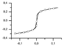 , 12
, 12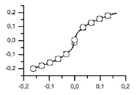 ).
).
 |
Fig. (11) Diagram stress-strain of aluminum alloy N.P.8. (squares) characterized using Marlow form of potential energy (circles) in ABAQUS/CAE®. |
 |
Fig. (12) Diagram stress-strain of annealed copper (squares) characterized using Marlow form of potential energy (circles) in ABAQUS/CAE®. |
Values obtained by the proposed algorithm and values calculated by ABACUS/CAE® are very close, as shown in Figs. (13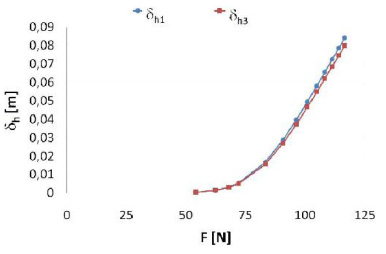 -16
-16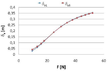 ). Some slight differences are due to the Marlow form of the potential used to characterize the proposed materials.
 |
Fig. (13) Horizontal deflections computed with the proposed algorithm (δ h1) and with ABAQUS/CAE® (δ h3) for a cantilever beam realized with NP8 aluminium alloy. |
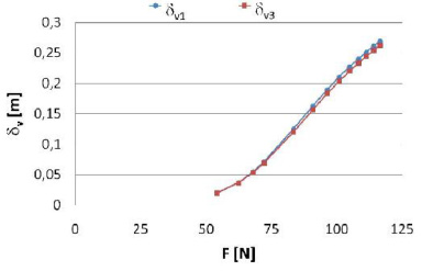 |
Fig. (14) Vertical deflections computed with the proposed algorithm (δ v1) and with ABAQUS/CAE® (δ v3) for a cantilever beam realized with NP8 aluminium alloy. |
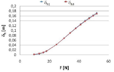 |
Fig. (15) Horizontal deflections computed with the proposed algorithm (δ h1) and with ABAQUS/CAE® (δ h3) for a cantilever beam realized with annealed copper. |
 |
Fig. (16) Vertical deflections computed with the proposed algorithm (δ v1) and with ABAQUS/CAE® (δ v3) for a cantilever beam realized with annealed copper. |
CONCLUSION
This work proposed a solution for the problem of the computation of the vertical and horizontal deflections of the free end in a cantilever beam composed by Luwick material under the effects of a vertical constant load positioned at the free end. The problem consisted in a non-linear algebraic system coupled with a non-liner second order ordinary differential equation, where non-linearities are due to the material and the geometry. It was solved with a Newton-Raphson method in cascade with an Eulerian approach and the results were verified with FEM software agreeing with it and with those in literature. Finally, the results were discussed to the role of material coefficients in the analysis of large deformations.
NOMENCLATURE
CONFLICT OF INTEREST
The authors confirm that this article content has no conflict of interest.
ACKNOWLEDGEMENTS
Declared none.
REFERENCES
| [1] | F. Guan, C. Zhou, and Q. Huang, "An innovative planetary gear reducer with overcoming the “dead point”", Open Mech. Eng. J., vol. 7, pp. 70-75, 2013. [http://dx.doi.org/10.2174/1874155X01307010070] |
| [2] | J. Huo, S. Yu, J. Yang, and T. Li, "Static and dynamic characteristics of the chain drive system of a heavy duty apron feeder", Open Mech. Eng. J., vol. 7, pp. 121-128, 2013. [http://dx.doi.org/10.2174/1874155X01307010121] |
| [3] | B. Li, X. Yao, Y. Li, W. Tan, H. Lou, and D. Ge, "Simulation & optimization for the gear system of a 6-DOF manipulator using flexible dynamic of ANSYS", Open Mech. Eng. J., vol. 8, pp. 69-76, 2014. [http://dx.doi.org/10.2174/1874155X01408010069] |
| [4] | Y. Wang, Z. Yang, L. Li, and X. Zhang, "The equation of meshing of spiral bevel gears manufactured by generating-line method", Open Mech. Eng. J., vol. 5, pp. 51-55, 2011. [http://dx.doi.org/10.2174/1874155X01105010051] |
| [5] | D. Yang, H. Cui, X. Tian, Q. Zhang, and P. Xu, "Research on tooth modification of spur bevel gear", Open Mech. Eng. J., vol. 5, pp. 68-77, 2011. [http://dx.doi.org/10.2174/1874155X01105010068] |
| [6] | E. Armentani, F. Caputo, and R. Citarella, "Fem sensitivity analyses on the stress levels in a human mandible with a varying atm modelling complexity", Open Mech. Eng. J., vol. 4, pp. 8-15, 2010. |
| [7] | C. Li, S. Zhou, S. Yang, X. Ren, and B. Wen, "Dynamic characteristics of blade-disk-rotor system with structural mistuned features", Open Mech. Eng. J., vol. 8, pp. 138-143, 2014. [http://dx.doi.org/10.2174/1874155X20140501008] |
| [8] | D. Liu, H. Zhang, Z. Tao, and Y. Su, "Finite element analysis of high-speed motorized spindle based on ANSYS", Open Mech. Eng. J., vol. 5, pp. 1-10, 2011. [http://dx.doi.org/10.2174/1874155X01105010001] |
| [9] | B. Zheng, Y. Liu, and R. Liu, "Stress and fatigue of connecting rod in light vehicle engine", Open Mech. Eng. J., vol. 7, pp. 14-17, 2013. [http://dx.doi.org/10.2174/1874155X01307010014] |
| [10] | K. Bisshopp, and D. Drucker, "Large deflection of cantilever beams", Q. Appl. Math., vol. 3, pp. 272-275, 1945. |
| [11] | C.C. Lo, and S. Das Gupta, "Bending of a nonlinear rectangular beam in large deflection", J. Appl. Mech., vol. 45, pp. 213-215, 1978. [http://dx.doi.org/10.1115/1.3424238] |
| [12] | G. Lewis, and F. Monasa, "Large deflections of cantilever beams of nonlinear materials", Comput. Struct., vol. 14, pp. 357-360, 1981. [http://dx.doi.org/10.1016/0045-7949(81)90054-7] |
| [13] | G. Lewis, and F. Monasa, "Large deflections of cantilever beams of non-linear materials of the Ludwick type subjected to an end moment", Int. J. Non-linear Mech., vol. 17, pp. 1-6, 1982. [http://dx.doi.org/10.1016/0020-7462(82)90032-4] |
| [14] | K. Lee, "Large deflections of cantilever beams of non-linear elastic material under a combined loading", Int. J. Non-linear Mech., vol. 37, pp. 439-443, 2002. [http://dx.doi.org/10.1016/S0020-7462(01)00019-1] |
| [15] | C. Baykara, U. Guven, and I. Bayer, "Large deflections of a cantilever beam of nonlinear bimodulus material subjected to an end moment", J. Reinf. Plast. Compos., vol. 24, pp. 1321-1326, 2005. [http://dx.doi.org/10.1177/0731684405049857] |
| [16] | E. Solano-Carrillo, "Semi-exact solutions for large deflections of cantilever beams of non-linear elastic behaviour", Int. J. Non-linear Mech., vol. 44, pp. 253-256, 2009. [http://dx.doi.org/10.1016/j.ijnonlinmec.2008.11.007] |
| [17] | M. Brojan, M. Cebron, and F. Kosel, "Large deflections of non-prismatic nonlinearly elastic cantilever beams subjected to non-uniform continuous load and a concentrated load at the free end", Acta Mech. Sin., vol. 28, pp. 863-869, 2012. |
| [18] | J.T. Holden, "On the finite deflections of thin beams", Int. J. Solids Struct., vol. 8, pp. 1051-1055, 1972. [http://dx.doi.org/10.1016/0020-7683(72)90069-8] |
| [19] | B.K. Lee, J.F. Wilson, and S.J. Oh, "Elastica of cantilevered beams with variable cross-sections", Int. J. Non-linear Mech., vol. 28, pp. 579-589, 1993. [http://dx.doi.org/10.1016/0020-7462(93)90049-Q] |
| [20] | G. Baker, "On the large deflections of nonprismatic cantilevers with a finite depth", Comput. Struct., vol. 46, pp. 365-370, 1993. [http://dx.doi.org/10.1016/0045-7949(93)90201-N] |
| [21] | G. Prathap, and T.K. Varadan, "Inelastic large deformation of beams", Trans. ASME, vol. 43, pp. 689-690, 1976. [http://dx.doi.org/10.1115/1.3423957] |
| [22] | T. Varadan, and D. Joseph, "Inelastic finite deflections of cantilever beams", J. Aeron. Soc. India, vol. 39, pp. 39-41, 1987. |
| [23] | Y.A. Kang, and X.F. Li, "Bending of functionally graded cantilever beam with power-law non-linearity subjected to an end force", Int. J. Non-linear Mech., vol. 44, pp. 696-703, 2009. [http://dx.doi.org/10.1016/j.ijnonlinmec.2009.02.016] |
| [24] | C. Amici, A. Borboni, and R. Faglia, "A compliant PKM mesomanipulator: kinematic and dynamic analyses", Adv. Mech. Eng., vol. 2010, p. 706023, 2010. |
| [25] | C. Amici, A. Borboni, R. Faglia, D. Fausti, and P.L. Magnani, "A parallel compliant meso-manipulator for finger rehabilitation treatments: kinematic and dynamic analysis", In: 2008 IEEE/RSJ International Conference on Robots and Intelligent Systems, vol. 1-3. Nice: France, 2008, pp. 735-740. [http://dx.doi.org/10.1109/IROS.2008.4651029] |
| [26] | A. Borboni, and R. Faglia, "Stochastic evaluation and analysis of free vibrations in simply supported piezoelectric bimorphs", J. Appl. Mech., vol. 80, no. 2, 2013. [http://dx.doi.org/10.1115/1.4007721] |